HIGHFIDELITY DESIGN METHODS TO DETERMINE KNOCKDOWN FACTORS FOR THE
HIGHFIDELITY DESIGN METHODS TO DETERMINE KNOCKDOWN FACTORS FOR THE
Title of paper
High-fidelity design methods
to determine knockdown factors for the buckling load of axially
loaded composite cylindrical shells
H.N.R.
Wagner, C. Hühne, S. Niemann, L. Weiß
German Aerospace Center, Braunschweig, Germany
ABSTRACT: The design of thin-walled structures still relies on
empirical guidelines like the NASA SP-8007 for cylinders up till
now. This lower-bound guideline does not include important
mechanical properties of laminated composite materials, such as the
stacking sequence. New design approaches that allow taking full
advantage of composite materials are therefore required.
Within
this paper newly developed innovative design approaches for axially
loaded cylindrical shells are presented and validated by means of
high-fidelity buckling experiments of unstiffened composite
cylinders. The considered composite shells were designed,
manufactured and tested at the German Aerospace Center (DLR) in
Braunschweig. The results show that the buckling load can be
determined very accurately in contrast to the previous methodology.
1Introduction
1.1State-of-the-Art
The maximum load carrying capacity of thin-walled cylindrical shells under axial compression, the buckling load Nper (see Figure 1), is reduced significantly by imperfections. Geometric imperfections reduce the buckling load of unstiffened cylindrical shells (Koiter 1945) and are defined as shape deviations from the ideal structure. However, the buckling load of cylindrical shells is reduced not only by traditional geometric imperfection, but also by non-traditional imperfections like loading imperfections. Loading imperfections are defined as the deviation from the perfect homogenous load introduction of a cylinder.

Figure 1. Load-displacement curve and corresponding buckling loads of an unstiffened cylindrical shell
The buckling load reduction is represented by means of a knockdown factor (KDF) which is defined as the ratio of the buckling load Nimp of an imperfect shell to the theoretical buckling load Nper of a perfect shell. There is a huge collection of experimental data for axially loaded composite cylindrical shells shown in Figure 2. The results show that the KDFs range mainly from exp = 0.6…0.9 and in some few cases are even below exp = 0.5.
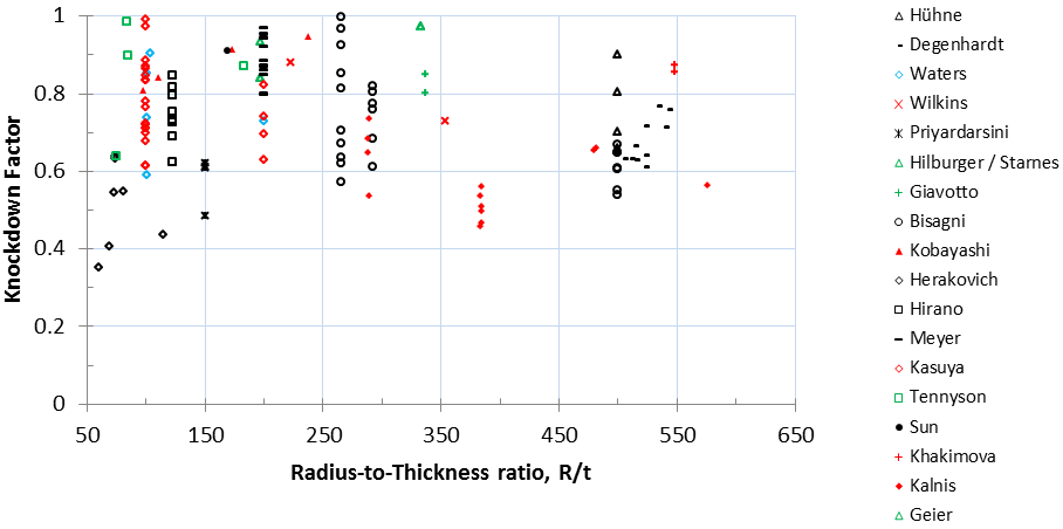
Figure 2. Distribution of the experimental data of axial compressed composite cylindrical shells for different R/t ratios (Wagner et al. 2017a)
Due to the significant differences between buckling theory and corresponding empirical data, the design of cylindrical shells relies on the application of empirical knockdown factors. An empirical design guideline is the NASA SP-8007 (Peterson et al. 1968) for cylindrical shells which represent a statistical lower bound of different experimental data from the beginning of the 20th century. The KDFs of the NASA SP-8007 are very conservative for modern shell structures (Hilburger et al. 2002). Therefore researchers developed new approaches for the development of KDFs for the buckling load.
Within this paper, a new innovative and physical based design procedure is presented for axially loaded cylindrical shells.
It is possible to consider either the combined influence of geometric and loading imperfections or only the influence of geometric imperfections on the buckling load within this design procedure.
The new design approaches are validated by means of high-fidelity experimental results of unstiffened composite cylindrical shells.
1.2Test Specimen
The composite cylinders (Z36-Z37) considered were designed, manufactured and tested at the German Aerospace Center (DLR) in Braunschweig (Khakimova et al. 2017). The corresponding nominal material as well as geometry data is given in Table 1.
Table 1. Geometry and material data for the composite cylindrical shells Z36-Z37 (Khakimova et al. 2017)
______________________________________________
Laminate Stacking Sequence [34, -34, 0, 0, 53, -53]
______________________________________________
Material Parameter Geometry Parameter
______________________________________________
E11 [MPa] 152400 R [mm] 400
E22 [MPa] 8800 L [mm] 800
G12 [MPa] 4900 t [mm] 0.75
G23 [MPa] 3230 R/t [-] 533
[-] 0.31 L/R [-] 2
_____________________________________________
2High-fidelity methods
2.1Introduction
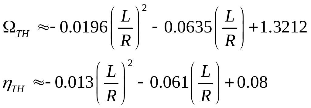
The shells Z36-Z37 are analyzed in this section with the new high-fidelity design methods which were developed at the German aerospace center in Braunschweig (Wagner et al. 2017). The influence of realistic geometric imperfections can be assessed with the single perturbation displacement approach (SPDA) whereas the combined influence of geometric and loading imperfections can be assessed with the single boundary perturbation approach (SBPA). These methods offer a physical based estimation of the lower-bound buckling load and are easy to implement as well as independent from imperfection measurements. However, they rely on geometrically non-linear finite element simulations which are time consuming and costly. Therefore, an analytical equation for the lower-bound buckling load which is based on curve fitting of lower-bound KDFs for isotropic shells with the SBPA.
![]() (1)
(1)
 (2)
(2)
Equation 1 for the threshold KDFs (TH) deliver accurate estimations of the lower-bound buckling bound for isotropic and quasi-isotropic composite shells with:
1. L/R ~ 1…3
2. R/t ~ 50…600
3. clamped boundary condition
4. linear elastic material behavior
For axially stiff composite shells like Z36, equation 1 delivers slightly more conservative estimations for the lower-bound buckling load, which are still significantly higher than the KDFs proposed by the NASA SP-8007.
2.2Geometric Imperfections
The SPDA (Wagner et al. 2017) can be used to analyze the influence of realistic geometric imperfections (MSI) on the buckling load.

Figure 3. Illustration of the SPDA in the numerical analysis
This method assumes that a local snap-through, a sudden dynamic transition of a small dimple to a diamond dimple cannot occur already in the pre-buckling range of the shell under axial compression (Wagner et al. 2017).

Figure 4. Illustration perturbation reaction force RF vs. perturbation displacement v (left) buckling load N vs. perturbation reaction force RF (right)
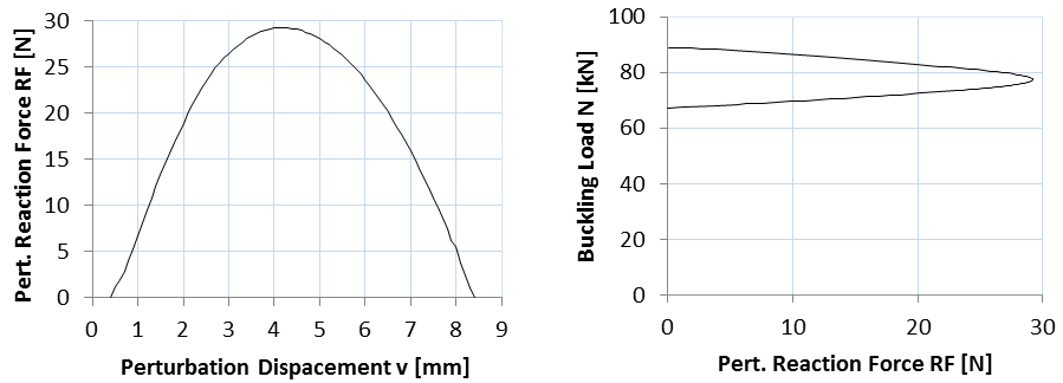
Figure 5. Perturbation reaction force RF vs. perturbation displacement v (left) buckling load N vs. perturbation reaction force RF (right) for Z36
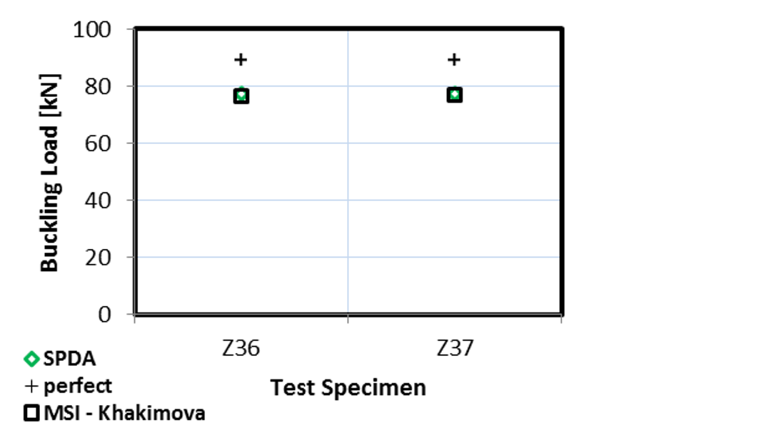
Figure 6. Buckling load for the shells Z36-Z37: perfect shell, design load according to SPDA, numerical buckling load with measured imperfections
Table 2. Buckling loads and knockdown factors for the composite cylindrical shells Z36-Z37 (Khakimova et al. 2017)
_______________________________
Shells Z36 Z37
_______________________________
Nper [kN] 88.94 88.94
NMSI [kN] 76.40 77.00
NSPDA [kN] 76.20 76.20
SPDA [-] 0.85 0.85
MSI [-] 0.85 0.87
_______________________________
The numerical model of the SPDA is illustrated in Figure 3. This approach induces a single dimple, which causes buckling, in a displacement controlled manner by means of the perturbation displacement v. Consequently, a special limit point can be identified by evaluating the corresponding reaction force RF (compare with Figure 4 – Figure 5). This limit point represents the threshold to the formation of a diamond dimple which is associated with a local snap-through (Wagner et al. 2017). The corresponding design load is defined as NSPDA and represents an accurate approximation of realistic geometric imperfections (see Table 2 and Figure 6).
2.3Geometric and loading imperfections
The SBPA (Wagner et al. 2017) was also derived from the basic idea of the SPLA and can be used to assess the combined influence of geometric and loading imperfections on the buckling load. This approach induces the single dimple, which causes buckling, by means of a boundary perturbation placed at the top shell edge (see Figure 7). A rigid plane moves in the direction of the cylinder axis and causes a single dimple right beneath the cylinder top edge. Under axial compression the single dimple moves gradually to the shell middle and increases its amplitude. This process is iterated for increasing boundary perturbation heights h which leads to the characteristic SBPA diagram (see Figure 8 - right).

Figure 7. Illustration of the SBPA in the numerical analysis
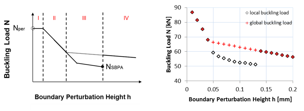
Figure 8. Illustration SBPA diagram for shells with ring pattern in the pre-buckling range (left) – SBPA diagram for Z36 (right)
The evaluation of this method considers the pre-buckling pattern of the shell. The shell Z36 has a ring pattern in the pre-buckling range (Khakimova et al. 2017), the corresponding lower-bound buckling load NSBPA (see Figure 9 and Table 3) is according to (Wagner et al. 2017) defined as the minimum local buckling load (see Figure 9 – left). This method assumes that a local snap-through event in the pre-buckling range leads to a lower-bound buckling load. The lower-bound buckling load represents the threshold between the sudden dynamic formation of a diamond dimple and the gradual formation of the diamond dimple.
The shell compensates the local loss of axial stiffness, due to the diamond dimple, redistributing the membrane stresses along the cylinder circumference under axial compression. No time if left for the redistribution of the membrane stresses in the case of a sudden dynamic formation of a diamond dimple under axial compression, consequently the shell collapses at a low load level. If the dimple is huge, the shell behaves similar to a shell with a hole and the redistribution of the membrane stresses occurs gradually under axial compression, hence a higher collapse load can be reached.
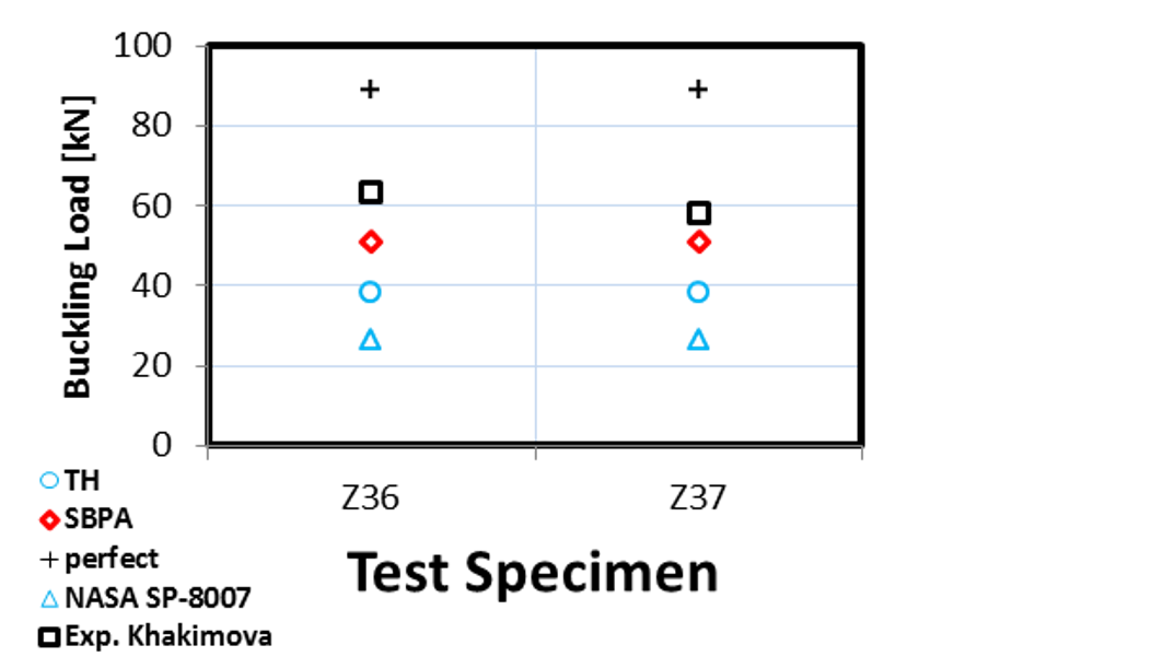
Figure 9. Buckling load for the shells Z36-Z37: perfect shell, design load according to SBPA, experimental buckling load
Table 3. Results of numerical analysis: buckling loads and knockdown factors for the composite cylindrical shells Z36-Z37
_______________________________
Shells Z36 Z37
_______________________________
Nper [kN] 88.94 88.94
NExp [kN] 63.30 58.30
NSBPA [kN] 51.19 51.19
NTH [kN] 38.24 38.24
NNASA [kN] 26.68 26.68
Exp. [-] 0.71 0.65
SBPA [-] 0.57 0.57
TH [-] 0.43 0.43
NASA [-] 0.30 0.30
_______________________________
2.4Comparison
In this section the shells Z36-Z37 were analyzed with high-fidelity design methods for cylindrical shells, the SPDA and the SBPA. The design load of the SPDA considers the influence of realistic geometric imperfections on the buckling load whereas the SBPA considers the influence of geometric and loading imperfections.
The design load NSPDA approximates the influence of the measured geometric imperfection on the buckling load very accurately (~1 %). From these results it is concluded that the buckling load is not reduced by shape deviations as assumed in (Koiter 1945) but the buckling load reduction depends mainly on the single dimple (amplitude and position) which induces collapse.
The SBPA delivers a conservative design load with respect to the experimental data and is 92 % higher than the design load according to the NASA SP-8007.
The result of equation 1 gives a 43 % higher KDF than the NASA SP-8007. In the case of the axially stiff composite shells Z36-Z37 the difference between the correct numerical lower-bound and the analytical lower-bound is 25 %. This is due to the fact that the threshold KDFs are based on isotropic material, but as they can be determined with a simple analytic equation it is the cost of the computational time saved.
3conclusion
In the paper a new design criterion for cylindrical shells under axial compression is presented and validated by means of experimental results.
The presented perturbation approaches can be used either to approximate the combined influence of geometric and loading imperfection or only the influence of geometric imperfections on the buckling load.
The SPDA approximates the influence of realistic measured geometric imperfections with a deviation of about 1 %.
The SBPA delivers a conservative lower bound of the buckling load with respect to the experimental results. The corresponding KDF for the buckling load is about 92 % higher compared to the conventional used NASA SP-8007.
Reference
Koiter, Warner Tjardus. 1945. The Stability of Elastic Equilibrium [PhD thesis in Dutch]. Englisch Translation NASA TTF-10. 1967. 1–833.
Peterson, J. P., Seide, P. und Weingarten, V. I. 1968. Buckling of thin-walled circular cylinders - NASA SP-8007. NASA Langley Research Center. Technical Report.
Hilburger, M. and Starnes, J. 2002. "Effects of Imperfections on the Buckling Response of Compression loaded Composite Shells," International Journal of Non-linear Mechanics 37: 623-643,
Khakimova, R., et al. 2017. Buckling of axially compressed CFRP cylinder with and without addtional lateral load: experimental and numerical investigation. Thin-Walled Structures, accepted
Wagner, H.N.R., et al. 2017a. Robust design criterion for axially loaded cylindrical shells - Simulation and Validation. Thin-Walled Structures 115: 154-162.
Wagner, H.N.R., et al. 2017b. Robust knockdown factors for the design of axially loaded cylindrical and conical composite shells - Development and Validation. Composite Structures 173: 281-303.
Hühne, C., et al. 2008. Robust design of composite cylindrical shells under axial compression - simulation and validation. Thin-Walled Structures 46: 947-962.
Tags: design methods, robust design, highfidelity, design, knockdown, factors, methods, determine
- Dpkocpdddcpo2003001 Dpkomd0300994 Dpkocpdddcpo2003001 Dpkomd0300994 Directives for Disciplinary Matters
- REGULAMENT CONCURS DE ELEGANȚĂ SINAIA – 29 IUNIE 2019
- ROLE OF THE GUT IN VISCERAL FAT INFLAMMATION AND
- FORM –
- AL MEDIODÍA EL SOL CONVIERTE EL LUGAR EN UN
- PARAIŠKA VEKSELIUI I DALIS PRAŠOMA SUMA
- DEPARTMENT OF VETERANS AFFAIRS M211 PART V SUBPART I
- FIN 335 EXAM III SPRING 2008 FOR DR GRAHAM’S
- “PUSE LA FRENTE ENTRE LAS OLAS PROFUNDAS DESCENDÍ COMO
- CARTAS EMPRESARIALES CARACTERÍSTICAS SE REMITEN FUERA DE LA
- 4 ANSWER TRUE OR FALSE TO THE NEXT 15
- GRANT CONTRACTS AWARDED DURING DECEMBER 2008 FINANCING SOURCE [DCIALA19189]
- AUTOSHAPE 11 AUTOSHAPE 11 AUTOSHAPE 11
- REGULAMIN PRACY W PRZEDSZKOLU SAMORZĄDOWYM NR 31 W
- COMISIÓN DE VIVIENDA Y CONSTRUCCION COMISIÓN DE VIVIENDA Y
- ANMELDUNG EINER VERANSTALTUNG GEM IV ABSCHNITT BGLD VERANSTALTUNGSGESETZ AN
- ZAŁĄCZNIK NR 1 DO ZAPYTANIA OFERTOWEGO ZNAK ZP271552018 FORMULARZ
- TENDRING DISTRICT COUNCIL TELECOMMUNICATIONS REGISTER SITES WITH PLANNING PERMISSION
- UNIVERSIDADE FEDERAL DO PARÁ PRÓREITORIA DE PESQUISA E PÓSGRADUAÇÃO
- LIKABEHANDLINGSPLANEN – ETT LEVANDE DOKUMENT I SKOLAN ETT SÄTT
- Sesión 3 Hecho en el Mundo Datos Fácticos y
- ESCUELA OFICIAL DE IDIOMAS DE SANTA BRÍGIDA CAMINO LOS
- REPUBLIKA MAKEDONIJA SOBRANIE NA REPUBLIKA MAKEDONIJA KOMISIJA ZA
- SLADKÉ DEZERTY A SLANÉ CHUŤOVKY RÝCHLO A ZA
- REGULADOR ELECTRÓNICO DE POTENCIA PUEDEN SER DE 400
- KATECHEZA 8 SŁUCHAMY BOGA W JEGO ŚWIĄTYNI
- FSH 150911 GRANTS AND AGREEMENTS HANDBOOK 185 R6
- 6 PODELITEV PRIZNANJ ZA NAJBOLJŠE INOVACIJE SAŠA REGIJE ZA
- MOBILE PHONE POLICY MOBILE PHONE POLICY INTRODUCTION THE USE
- EMERGENCY TRIAGE EDUCATION KIT
 PRILOG 10 OBRAZAC Z ETDMPV ZAHTJEV ZA IZDAVANJE ODOBRENJA
PÁRRAFO 10 ENTRE CORCHETES (BRASIL) [TAMBIÉN REAFIRMAMOS NUESTRO INTERÉS
 FAIRHILLS PRIMARY SCHOOL SCHOOL COUNCIL ELECTION INFORMATION FOR
 ARAÇ KONTROL BİRİMİ ALTERNATİF YAKIT SİSTEMİYLE ÇALIŞAN ARAÇLARDA DENETİM
 KGATELOPELE LOCAL MUNICIPALITY INDIGENT SUBSIDY POLICY 20172018 P R
 B UILDING BETTER OPPORTUNITIES STAGE TWO – PARTNERSHIP INVOLVEMENT
 IZRAVNA PRODAJA U HRVATSKOJ U HRVATSKOJ JE IZRAVNA
PANDUAN HIBAH PENULISAN DAN PENERBITAN BUKU AJAR
PLIEGO DE CONDICIONES QUE REGIRÁ EL ACUERDO MARCO PARA
ALGUNOS CAMINOS POLÍTICAMENTE INCORRECTOS A TRAVÉS DE LO POLÍTICAMENTE
 “2008 AÑO DE LA ENSEÑANZA DE LAS CIENCIAS”
 WYKAZ OFEROWANYCH URZĄDZEŃ – CZĘŚĆ 1 PRZEDMIOTEM ZAMÓWIENIA JEST
 T EMARIO TEMARIO 1 INTRODUCCIÓN PROBLEMÁTICA 2 SEGURIDAD EN
IN SUPPORT OF ANTIINTELLECTUALISM ABSTRACT MUCH OF THE RECENT
22 ZAŁĄCZNIK DO UCHWAŁY NR 32020 ZARZĄDU PFRON Z
KANT’S HISTORY OF ETHICS ALLEN W WOOD STANFORD UNIVERSITY
RESEARCH INITIATIVE PLAN TEMPLATE REQUIRED FORM FOR BUSINESS INCUBATOR
 BUPATI KUNINGAN PERATURAN BUPATI KUNINGAN NOMOR 20 TAHUN 2012
 AN ROINN OIDEACHAIS AGUS EOLAÍOCHTA DEPARTMENT OF EDUCATION AND
ATTACHMENT 9 – INCIDENT MANAGEMENT REPORT (IMR) SAMPLE INCIDENT
