A MICROFLUIDIC PERFUSION PLATFORM FOR CULTIVATION AND SCREENING STUDY
A MICROFLUIDIC PERFUSION PLATFORM FOR CULTIVATION AND SCREENING STUDYSUPPLEMENTAL INFORMATION A MICROFLUIDIC CHIP FOR DETECTING CHOLANGIOCARCINOMA CELLS
A microfluidic perfusion platform for cultivation and screening study of motile microalgal cells
Young-Jae Eu,1,2,a) Hye-Sun Park1, 2,a) and Dong-Pyo Kim2,b) Jong Wook Hong3,4,b)
1Department of Fine Chemical Engineering and Applied Chemistry, Chungnam National University, Daejeon, 305-764, Korea
2National Center of Applied Microfluidic Chemistry, Department of Chemical Engineering, Pohang University of Science and Technology, Pohang, Gyungbuk, 790-784, Korea
3Materials Research and Education Center, Department of Mechanical Engineering, Auburn University, Auburn AL, 36830, USA
4Department of Bionano Engineering, Hanyang University, Ansan, 427-791, Korea.
a)Y.-J. Eu and H.-S. Park contributed equally to this work.
b)Authors to whom correspondence should be addressed. Electronic mail: [email protected] or [email protected].
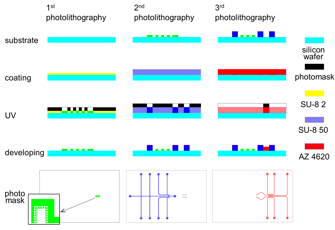
Fig. S1. The perfusion barrier of 2 m thickness was produced with SU-8 2 in the first photolithography. The second photolithography was conducted with SU-8 50 to produce the right part of the fluidic channel with no valve function. A positive photoresist, AZ4620 was used in the last step to produce the chamber and channel with valve function. The simple scheme of the used photomask for each photolithography step is shown at the bottom line, and the photomasks (left, middle) for negative photoresist are presented by inverting the black/white. The enlarged photomask pattern for perfusion barrier was shown in the inset.
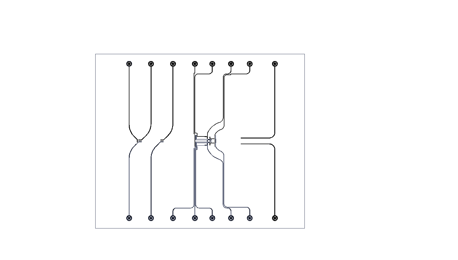
Fig. S2. A pattern of photomask for fabricating pneumatic valves
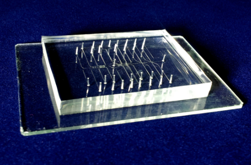
Fig. S3. PDMS based microfluidic perfusion chip fabricated by multilayer soft lithography method.
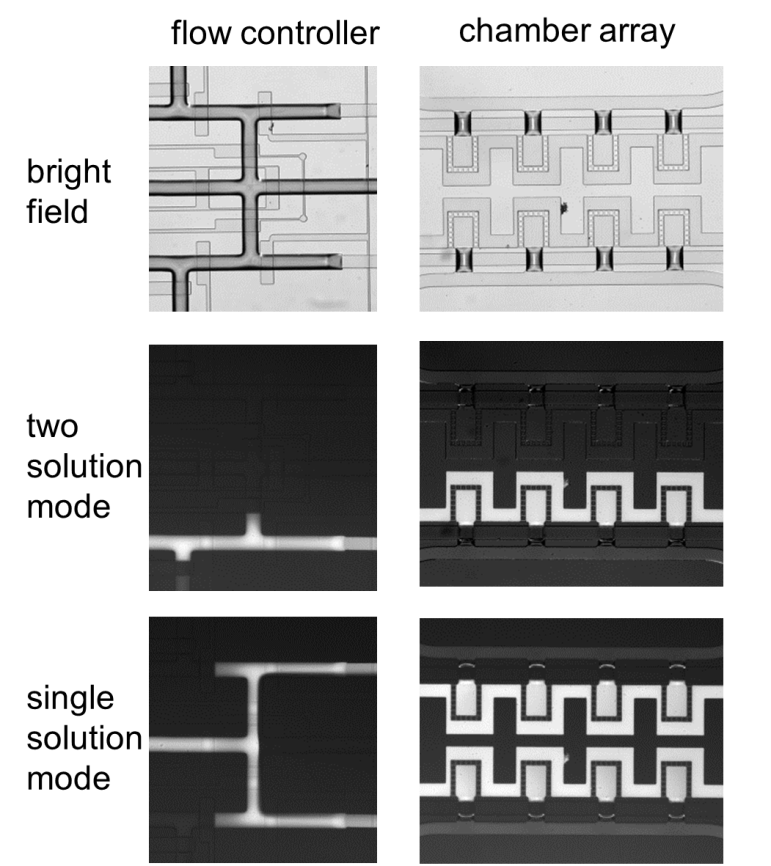
Fig. S4. Flow controller with combination of valves regulates the perfusion of medium into the microchamber array. Flows of two different solutions (middle) or single solution were visualized using water and fluorescent dye solution.
Fig. S5. Comparative perfusion kinetics of fluorescent dye into perfusion chamber with (a) symmetric channel width (90 m) and (b) asymmetric channel width (30 and 90 m) of inlet and outlet. The black and blue lines are the changes of the relative fluorescence intensities of the fluidic channel and chamber, respectively.
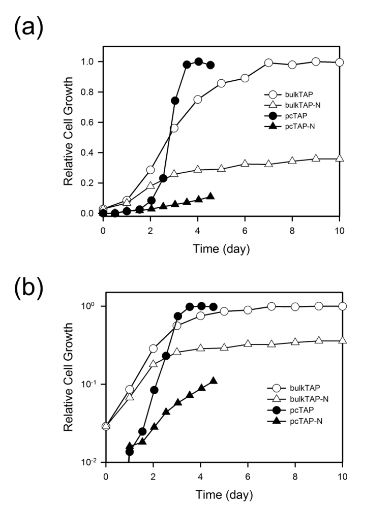
Fig. S6. Growth curve of Chlamydomonas cells in the TAP media in the N-replete and N-starved conditions cultivated in bulk or microfluidic perfusion chamber. The cells were cultivated in shaking flask or in microfluidic perfusion chamber under light of 2000 lux at room temperature. The growth in bulk was measured using absorbance at 600 nm and normalized to the maximum growth. The relative cell growth was shown in linear (a) and log scale (b). Shown is the representative growth curve of three independent experiments.
Tags: cultivation and, screening, platform, perfusion, cultivation, microfluidic, study
- 37 MODERATION OF TEACHER EXPECTATIONS EFFECTS RUNNING HEAD MODERATION
- EN PRÉSENCE DE QUANTITÉS CROISSANTES DE DIOXYDE DE CARBONE
- ULTIMA REFORMA DECRETO 220 PO 7 SUPL 3 09
- F EDERACIÓN DE BANDAS DE MÚSICA DE LA REGIÓN
- 8 REFERENC LISTA REFERENCES LIST ELASTOMERNA LEŽIŠTA
- CONDICIONES PARA LA PRESTACIÓN DEL SERVICIO DE CAFETERÍA EN
- BADANIA OPERACYJNE – PRZYKŁADOWE ZADANIA EGZAMINACYJNE ZESTAW A
- ”JURYEN GÅR INN FOR Å NOMINERE OSMAN MOHAMED ADEN
- 23 GOBIERNO DE CHILE MINISTERIO DE RELACIONES EXTERIORES DIRECCIÓN
- CIAO A TUTTI HI EVERY TAMPIER MY LITTLE
- ART ABOVE FARM MACHINERY SAFETY AND YOUR
- NEWS RELEASE FOR IMMEDIATE RELEASE CONTACT JODEE
- PERATURAN MENTERI DALAM NEGERI NOMOR 4 TAHUN 2008 TENTANG
- 8 8 RIC N 762004 REPUBBLICA ITALIANA IN
- PERFORMANCE EVALUATION BETWEENMEAL SUPPLEMENTS & SNACKS FEEDING ASSISTANCE DATE
- SOP STANDARD OPERATING PROCEDURES NUMBER DATE AUTHOR APPROVED BY
- HIGHER EDUCATION LEARNING AGREEMENT FORM STUDENTTRAINEE’S NAME SECTION TO
- 8 UNA TEORÍA MOMENTÁNEA DEL LENGUAJE DDAVIDSON MARÍA
- DUAL EMPLOYMENT REQUEST PERDE1 REV 799 STATE OF CONNECTICUT
- SAFETY ALARMS AT CERN P CIRIANI L HENNY P
- ANNEX 1 RU DETAILED COMMENTS (ALL THE AMENDMENTS SEE
- 8 POLICY ON DEPUTATION ABROAD (FOR STAY ABROAD BEYOND
- UNIVERSIDAD DE OVIEDO LA CASA DE LAS LENGUAS C
- BRASSMASTERS PO BOX 1137 SUTTON COLDFIELD WEST MIDLANDS
- DA 1150 RELEASED JANUARY 11 2011 ANNOUNCEMENT OF RECHARTERING
- 8 CAPÍTULO I 1 ASPECTOS GENERALES DEL ÁREA PROTEGIDA
- ROLA I MIEJSCE ORGANÓW ADMINISTRACJI PUBLICZNEJ W REALIZACJI ZADAŃ
- 32 FACULTAD DE CIENCIAS POSTÍTULO EN CIENCIAS NATURALES Y
- PLAN DE BANDAS DE LA IARU REGION 1 18
- SUPPORTING FAMILIES TO OPTIMALLY FEED INFANTS AND YOUNG CHILDREN
PITDAE4A CONTRATO DE PRESTACIÓN DE SERVICIOS PARA LA OBTENCIÓN
 PROBLEMAS DE MECÁNICA VECTORES 5VECTORES 1 ENCONTRAR LA COMPONENTE
 PERSONNEL ACTION FORM EMPLOYEE ID JOB NO EFFECTIVE DATE
SILVER LININGS 2011 NAME OF TOPIC MANAGING SIDE EFFECTS
 OGŁOSZENIE O ZAMÓWIENIU SZANOWNI PAŃSTWO DEPARTAMENT FUNDUSZY EUROPEJSKICH ZAPRASZA
MALAS PRÁCTICAS Y DEFICIENCIAS NORMATIVAS DENUNCIADAS EN EL INFORME
OFERTA USŁUG REGIONALNEJ AGENCJI PRODUCENCKIEJ I PRODUKCJA TELEDYSKU PODSTAWOWA
PATOLOGIA ANAL REQUERIMIENTOS CONOCIMIENTOS ANATÓMICOS Y FUNCIONALES DE
VLADA REPUBLIKE HRVATSKE 2962 NA TEMELJU ČLANKA 206 STAVKA
CONSERVATION OF TRANSBOUNDARY BIODIVERSITY IN THE MINKÉBÉODZALADJA INTERZONE IN
EMPLOYMENT FACTSHEET JOB SEEKING RESOURCES ABOUT THIS FACTSHEET
 UNIVERSIDAD DE BURGOS SERVICIO DE RELACIONES INTERNACIONALES INFORMACIÓN PARA
WTGCW633 TNCW61 PÁGINA 7 ORGANIZACIÓN MUNDIAL DEL COMERCIO WTGCW633
 SENTENCIA DEL TRIBUNAL SUPERIOR DE JUSTICIA PAÍS VASCO (SALA
NICHOLAS CARR PLITKO (ŠTO INTERNET ČINI NAŠEM MOZGU) AMERIČKI
 ZAŁĄCZNIK NR 3 KARTA OCENY BIZNES PLANU KARTA OCENY
 LATÍN II UNIDAD Nº 8 LA TRANSMISIÓN DE LA
I GRUPA 1JEDNAKOKRAKI TROUGAO SA OSNOVICOM DUŽINE 2CM
 REMITTANCES FOR DEVELOPMENT? A CASE STUDY OF THE IMPACT
 POVODOM SVJETSKOG DANA DOSTOJANSTVENOG RADA 7 LISTOPADA
