ME211 – INSTRUMENTATION AND SOFTWARE APPLICATIONS INSTRUCTOR MR
ME211 – INSTRUMENTATION AND SOFTWARE APPLICATIONS INSTRUCTOR MR
Experiment 5: The Reed Switch

ME211 – Instrumentation and Software Applications
Instructor: Mr. Charalambos Athanasiou
LABORATORY REPORT No. 4
The Variable Area Capacitance
|
Student’s Name: |
|
|
Reg. Num.: |
Date: |
4. Experiment’s title: The Variable Area Capacitance
I. Objectives
On completion of this experiment you will:
Understand how a variable area capacitor attaches to a system to measure displacement.
Have produced a calibration graph of output against displacement and made judgements on such characteristics as linearity, repeatability, accuracy and sensitivity.
Appreciate the sources of errors in capacitive circuits.
II. Theory
A capacitor is
an electrical component which stores charge when an e.m.f. is present
across it's terminals. Figure 1 shows a common type of capacitor
formed by two parallel plates.
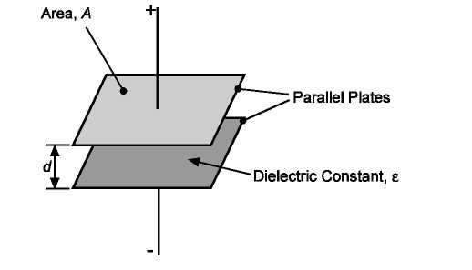
Figure 1
T![]()
his
example shows the plates being flat. In the SIS capacitance, and many
other types, the plates are parallel but formed by two concentric
cylinders separated by an insulating dielectric. In terms of
explaining how they work, treat them as being the same. The charge
storage capacity is a function of the capacitance of the device,
measured in Farads, and this may be determined from the equation:
where,
A = Area of overlap between plates: m2
eo = Permittivity of free space: 8.854 × 10⁻¹².Fm−1;
er = Relative permittivity of the dielectric material separating the plates: er for air is 1;
d = Distance between the plates: m.
Because of the magnitude of eo capacitance is, under all but exceptional circumstances, very small, usually measured in microFarads (mF) or picoFarads (pF).
If any or all of these parameters vary then the capacitance changes. In the variable capacitor used in the SIS the parameter chosen to be variable is the area of overlap of the plates. The capacitance varies in direct proportion to the area. By changing the area in direct proportion with displacement allows measurements of capacitance to be equated with displacement.
In the SIS, the variable area capacitor forms one arm of an a.c. bridge such that any change in capacitance produces an imbalance and this is converted directly into a D.C. signal at the output.
The object of this experiment is to investigate the use of a variable area capacitor to measure linear displacement.
III. Experimental Work
Part A: The Variable Capacitor Characteristics
Use the patching leads supplied to connect the equipment as shown in Figure 2. The front panel detail for the Capacitance Bridge shows the circuit schematically as a capacitance to voltage converter.
Move the Linear Assembly to the right by rotating the manual control clockwise until it reaches the end stop. Carefully adjust the dial until the zero aligns with the edge of the moulding. Use the 'set zero' control on the Capacitance Bridge to zero the reading on the meter.
In steps of 1 mm, one complete rotation of the rotary scale, move the Linear Assembly to the left over its full range of travel and record corresponding meter readings to complete Table 1. Be careful to adjust the control in one direction only throughout the procedure.
|
Displacement (mm) |
Output (V) |
|
0 |
|
|
1 |
|
|
2 |
|
|
3 |
|
|
4 |
|
|
5 |
|
|
6 |
|
|
7 |
|
|
8 |
|
|
9 |
|
Table 1: Results
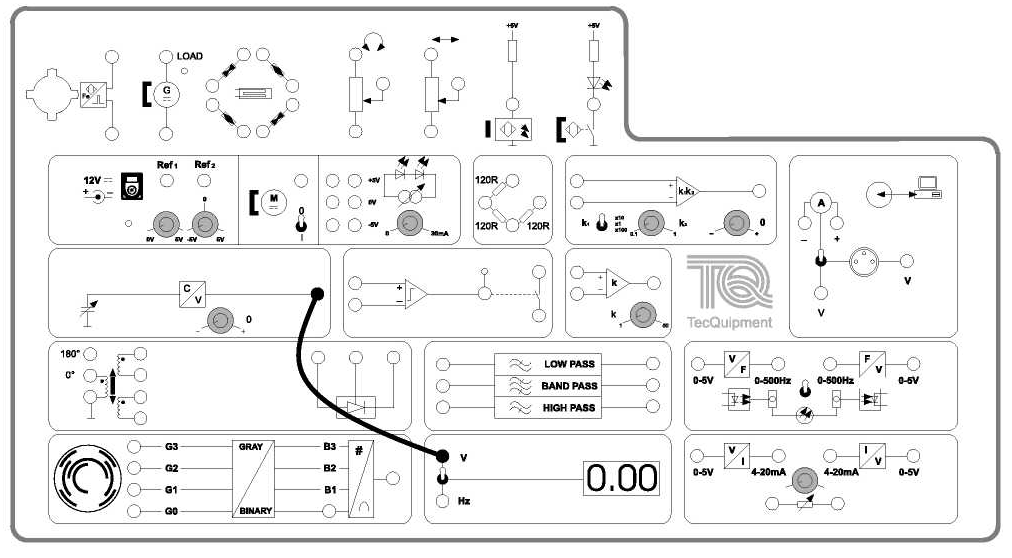
Figure 2: Output from the capacitance to voltage converter
Plot a graph of your results. Comment on the shape of the graph, measure its slope and intercept with the vertical axis. Give the equation governing this measurement system.
With the Linear Assembly adjusted to be in mid-position determine the minimum amount of movement (resolution) that can be detected by the meter reading.
Resolution = ……… mm
Part B: Variable Capacitor with Gain
Set the gain of the Differential Amplifier to 10 and then zero the output when the inputs are shorted together. Do not change these settings throughout the remainder of the experiment. Use the patching leads to connect the circuit as shown in Figure 3.
Use the 'set zero' control on the Capacitance Bridge to zero the reading on the meter once more. Repeat the previous procedure to complete Table 2.
Plot a graph of your results. Comment on the shape of the graph, and measure its slope and intercept with the vertical axis. From this, give the equation governing this measurement system.
With the Linear Assembly adjusted to be in mid-position, determine the minimum amount of movement (resolution) detectable by the meter reading.
Resolution =…………mm
Touch the body of the capacitor and observe the effect his has on the meter reading. Use one of the patching leads to connect the body of the capacitor to ground (0 V) and again observe the effect on the meter reading.
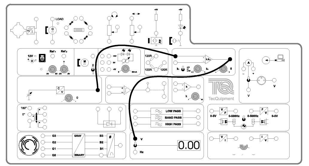
Figure
3:
Connection diagram for variable area capacitor with gain
|
Displacement (mm) |
Output (V) |
|
0 |
|
|
1 |
|
|
2 |
|
|
3 |
|
|
4 |
|
|
5 |
|
|
6 |
|
|
7 |
|
|
8 |
|
|
9 |
|
Table 2: Results
Part C: Use of the Comparator Circuit
The signals obtained in Parts A and B are analogue, in that they vary continuously with displacement to give a measure of position or change of position. This is in keeping with many types of sensor.
There are many applications where some positive action is required when a system reaches a predefined position, such as the limit stop on a piece of machinery. In others, it is the movement of a body in close proximity (near or touching) to the probe, which is sensed, and a response needed. This principle is used in touch switches, using the change of capacitance when touched to initiate an action.
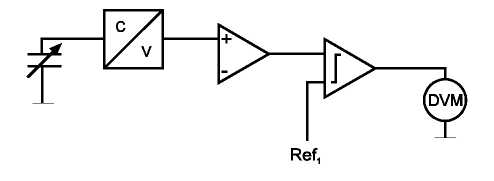
Figure 4: Variable area capacitor comparator circuit
The object of this experiment is to observe the effect of using a comparator at the output of the capacitance system to achieve controlled switching
.
The circuit is shown schematically in Figure 4. Using the results obtained in Part B, set Ref1 to the same voltage obtained when the Linear Assembly was in position 4 mm. Use the patching leads to connect the circuit as shown in Figure 5.
Starting with the Linear Assembly to the right, move it to the left and observe the meter reading over the full range of movement. Repeat the procedure with varying values of Ref1 over its complete range.
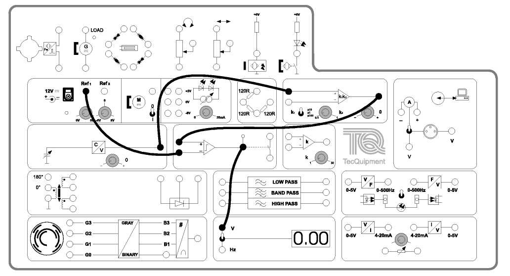
Figure 5: Connection diagram for variable area capacitor comparator circuit
IV. Comments and Conclusions
Describe how a variable area capacitor is designed and used to measure rotary displacement.
The maximum amount of relative
movement between the inner and outer
cylinders of the SIS
variable area capacitor is 9 mm. If the internal diameter of the
outer cylinder is 20.5 mm and the external diameter of the
inner cylinder is 19.05 mm,
calculate the change in
capacitance that occurs when the Linear Assembly is
moved over
the complete range.
Using the value calculated in step 2 and the results from Part B of this experiment, produce a calibration graph for the SIS variable area capacitor of displacement against capacitance to provide a means of direct capacitance measurement.
|
Displacement (mm) |
Capacitance (pF) |
|
0 |
|
|
1 |
|
|
2 |
|
|
3 |
|
|
4 |
|
|
5 |
|
|
6 |
|
|
7 |
|
|
8 |
|
|
9 |
|
Report:
Using the results obtained, observations made and the answers given to each of the questions in this experiment write a report on the use of the variable area capacitance for measuring linear displacement. Include any theory you feel supports the comments and conclusions you give.
Tags: applications instructor:, many applications, instrumentation, applications, software, instructor, me211
- СТАНОМ НА 05082016 МІСЦЕВИМИ ФІНАНСОВИМИ ОРГАНАМИ КИЇВСЬКОЇ ОБЛАСТІ ЗАЯВЛЕНО
- LOFA SOMMARFOTBOLL 2017 KVARTSFINAL DAM SÖNDAGEN DEN 9E JULI
- PORANEK ĆWICZENIA PORANNE WG SCHEMATU E ZAJĘCIE I
- 枕詞 ― みはかしを(御佩乎) この枕詞は劔にかかる。 御佩乎 劔池之 蓮葉に 渟有水之 往方無
- C URRICULUM VITAE INFORMAZIONI PERSONALI COGNOME E NOME ING
- DEAR FRIENDS WE ARE HAPPY TO INFORM YOU THAT
- DEPARTAMENTO DE DESARROLLO RURAL Y MEDIO AMBIENTE COMPROMETIDO UN
- COTIDIANO NO XINGU HTTPWWWTERRABRASILEIRANETINDIGENAINDEXHTML EXISTE UMA ATIVIDADE CONSTANTE NAS
- WAT ZIJN UW RECHTEN EN PLICHTEN IN HET KADER
- PORTARIA Nº 92898 DE 23 DE OUTUBRO O DECRETOLEI
- DECLARACIÓN POR EL DESARROLLO RURAL DECLARACIÓN DE SEVILLA
- ENTRE EL SUEÑO Y LA REALIDAD UN SEGUNDO SE
- PRESIDENCIA DE LA NACIÓN SECRETARIA DE CULTURA COMISIÓN
- MODULO 5 LIBERACIÓN DE LOTES OBJETIVO GENERAL
- CONVENIO ESPECÍFICO DE COTUTELA INTERNACIONAL DE TESIS DOCTORAL ENTRE
- CURRICULUM VITAE MARIO PATRICIO URZÚA MANZUR SAN RAFAEL Nº
- POR ROBERTO MORENO PARA ARMAR CIRCUITOS DENTRO DE
- INFORMATIEBROCHURE AANWERVING P LOEGBAAS CONTAINERPARK AARD VAN DE AANSTELLING
- LECTURE FIVE CONCEPT MAP CAUSE CONTRIBUTING FACTORS SIGNS AND
- CURRICULUM VITAE D ATOS PERSONALES NOMBRES Y APELLIDO MARIO
- FORMULARIO DE LA DECLARACIÓN JURADA DEL PRODUCTOR FINAL EL
- DECRETO 1152000 DE 20 DE JUNIO SOBRE RESTAURACIÓN DEL
- LLAMADO A MÉDICO ASISTENTE FONDO NACIONAL DE RECURSOS EL
- ASL CAMP REGISTRATION FORM SATURDAY AUGUST 11TH TO FRIDAY
- ZAŁ NR 6 DO PROCEDURY WYBORU I OCENY GRANTOBIORCÓW
- LIETUVOS VAIKŲ (1998 M GIM IR JAUNESNIŲ MERGAIČIŲ BEI
- CURRICULUM VITAE A PERSONAL INFORMATION NAME NIZAR BAKIR YAHYA
- CURRICULUMVITAE DATOS PERSONALES APELLIDO Y NOMBRES YUNES
- (A GOVERNMENT OF INDIA UNDERTAKING) HO 112 J C
- POR UN MODELO DE COMERCIO URBANO EL COMERCIO ES
 INSTRUCTIVO RELACIONADO CON LA PRESENTACIÓN DE LA RENUNCIA PARA
 DOTTORATO IN BIOMATERIALI CICLO XVIII FACOLTÀ DI CHIMICA INDUSTRIALE
NAMEPERIOD COMPARISONCONTRAST ESSAY RUBRIC CATEGORY EXCEEDS THE STANDARD
INFORMATIONSBLATT FÜR NICHT ERKRANKTE SCHÜLERINNEN UND SCHÜLER IN DEREN
 LATVIJAS REPUBLIKA KRUSTPILS NOVADA PAŠVALDĪBA REĢNR90009118116 RĪGAS IELĀ 150A
 BESTILLING AV KLUBBDRAKTER STYRET I MÅREN OK VIL FORETA
PROLEĆNI AFFIDEA FESTIVAL ZDRAVLJA 5 I 6 APRIL 2017
ASZÓD VÁROS ÖNKORMÁNYZAT POLGÁRMESTERÉTŐL ELŐTERJESZTÉS KÖTVÉNY TŐKETÖRLESZTÉSÉHEZ SVÁJCI FRANK
ESTABLECE CUOTAS GLOBALES ANUALES DE CAPTURA PARA EL RECURSO
Karar No200912 Genel Müdürlük Makamina Tapu ve Kadastro
 SOLICITUD DE AYUDAS A PROYECTOS O PROGRAMAS DE ACTUACIÓN
AUSSCHREIBUNGSTEXT KRAMER VIA CAMPUS DRAHTLOSPRÄSENTATIONSSYSTEM FÜR GRUPPENARBEIT UND TRAINING
SCHURIG CENTER FOR BRAIN INJURY RECOVERY OFFICE MANAGER
INTRODUCCIÓN AL CASO PRÁCTICO PODERES EL ARTÍCULO 98
TEMATYKA I ORGANIZACJA SPOTKAŃ Z RODZICAMI UCZNIÓW ZESPOŁU OŚWIATOWEGO
39 VERITAS DRAFT ACCESS TO INFORMATION AND FREEDOM OF
ТАБЛИЦЯ 9 ДО РОЗД 1 РОЗД 3131 ОСНОВНІ ПОКАЗНИКИ
 INŠTITUT ZA ŠPORT CENTER ZA VSEŽIVLJENJSKO UČENJE V ŠPORTU
 YÜKSELEN SÜRÜCÜ KURSU – SERDAR KUÇHAN 2014 ARAÇ KULLANIM
 HELIDROMI SA SAGLASNOŠĆU ZA KORIŠĆENJE REDNI BROJ NAZIV HELIDROMA
