ALMA MEMO NO 504 THE CLOUDSAT RADAR AND IMPLICATIONS
ALMA MEMO NO 504 THE CLOUDSAT RADAR AND IMPLICATIONS
Draft technical memo on Cloudsat
ALMA Memo No. 504
The CloudSat Radar and Implications for ALMA
A report from the ALMA North American Technical Advisory Committee (ANATAC)
Submitted on behalf of ANATAC by Darrel Emerson, National Radio Astronomy Observatory,
949 N. Cherry Ave., Tucson, AZ 85721.
2004-08-23
Abstract
CloudSat is a downward-looking 94 GHz satellite-borne radar, due for launch in April 2005. The peak EIRP of the radar beam is some 4.109 watts, which is sufficient to damage ALMA receivers on the ground if ALMA antennas and the orbiting radar ever look directly at each other. Although the likelihood of this happening is very small, ALMA does need to take some operational precautions to avoid receiver damage, and to flag data that will be contaminated by radar interference.
The CloudSat Mission
At the 1997 WRC in Geneva, a US proposal to allocate the band 94.0 to 94.1 GHz for spaceborne radars, which determine the vertical profile of clouds and their global distribution, was accepted. This band is now allocated internationally to “EARTH EXPLORATION SATELLITES (active),” but is nevertheless shared with Radio Astronomy. ITU footnote 5.562 says:
5.562 The use of the band 94-94.1 GHz by the Earth exploration-satellite (active) and space research (active) service is limited to spaceborne cloud radars
while footnote 5.562A says:
5.562A In the bands 94-94.1 GHz and 130-134 GHz, transmissions from space stations of the Earth exploration-satellite service (active) that are directed into the main beam of a radio astronomy antenna have the potential to damage some radio astronomy receivers. Space agencies operating the transmitters and the radio astronomy stations concerned should mutually plan their operations so as to avoid such occurrences to the maximum extent possible.
At the time these ITU regulations were being considered, there were some studies made to consider the impact on radio astronomy. In particular, John Ponsonby (Reference [1]) made some detailed calculations of the conditions under which such systems would or would not impact radio astronomy.
CloudSat is the first spaceborne radar to make use of this allocation. It is part of the “A-train” constellation, consisting of 5 satellites, most of which (apart from CloudSat) are passive sensing satellites. In order of orbital formation, the satellites are Aqua, CloudSat, Calipso, Parasol and Aura. Aqua and Aura are already in orbit, with CloudSat itself now to be launched in April 2005. All satellites will have similar orbits, arranged specifically to have identical ground tracks, separated by only some seconds of time. Details of the scientific mission were given in 2002 in Reference [2], whose abstract reads:
CloudSat is a satellite experiment designed to measure the vertical structure of clouds from space. The expected launch of CloudSat is planned for 2004, and once launched, CloudSat will orbit in formation as part of a constellation of satellites (the A-Train) that includes NASA's Aqua and Aura satellites, a NASA–CNES lidar satellite (CALIPSO), and a CNES satellite carrying a polarimeter (PARASOL). A unique feature that CloudSat brings to this constellation is the ability to fly a precise orbit enabling the fields of view of the CloudSat radar to be overlapped with the CALIPSO lidar footprint and the other measurements of the constellation. The precision and near simultaneity of this overlap creates a unique multisatellite observing system for studying the atmospheric processes essential to the hydrological cycle.
The vertical profiles of cloud properties provided by CloudSat on the global scale fill a critical gap in the investigation of feedback mechanisms linking clouds to climate. Measuring these profiles requires a combination of active and passive instruments, and this will be achieved by combining the radar data of CloudSat with data from other active and passive sensors of the constellation. This paper describes the underpinning science and general overview of the mission, provides some idea of the expected products and anticipated application of these products, and the potential capability of the A-Train for cloud observations. Notably, the CloudSat mission is expected to stimulate new areas of research on clouds. The mission also provides an important opportunity to demonstrate active sensor technology for future scientific and tactical applications. The CloudSat mission is a partnership between NASA's JPL, the Canadian Space Agency, Colorado State University, the U.S. Air Force, and the U.S. Department of Energy.
Technical details of CloudSat
The CloudSat radar operates at 94.05 GHz, from a sun synchronous polar orbit with a height of 705 km; the ground tracks of the orbit (see below) repeat precisely every 16 days. Peak radar transmitter power is 1800 watts, degrading to 1500 watts at the end of its lifetime, into an antenna with 63 dBi gain, giving approximately 4.109 watts effective radiated power (EIRP). Polarization is linear. The radar points along the geodetic nadir within 0.07 degrees. The nominal footprint of the radar beam on the ground is ~1.4 km in diameter, but the extent of the footprint to the first nulls in the pattern is 3 km. Pointing knowledge is 0.053 degrees and pointing control is around 1 km. [Note that ALMA, with a diameter of 14 km, subtends an angle of 1.14 degrees as seen from the satellite.] The actual ground track may have a cross-track error +/-10 km, caused by an unpredictable component of atmospheric drag perturbing the orbit. The radar pulse length is approximately 3.3 microseconds, and the pulse repetition frequency (PRF) varies from 3700 to 4300 Hz, giving mean radar transmitter power of about 25 watts. The second and third harmonics of the transmitter are given as respectively 50 dB and 60 dB below the fundamental.
The CloudSat antenna is an offset parabola and has a beamwidth of 0.108 degrees, with a boresight gain of 63 dBi. The distance to first null in the pattern is +/-0.125 degrees. The first major sidelobe, 0.2 degrees from boresight, has a gain of 47 dBi. The antenna gain reaches 0 dBi at about +/-6.4 degrees, and beyond about +/-11 degrees the antenna response is no greater than about -12 dBi.
Because the radar beam is always directed downwards, along the local gravitational vector, the only possibility of ALMA antennas looking directly into the radar beam is if they are pointed at the zenith, as the radar flies directly over the site. This is an unlikely occurrence. The CloudSat beam will occasionally be directed away from the nadir, for calibration purposes, but this measurement will always be carried out over ocean, so should not be an issue for ALMA.
Further technical details of CloudSat are given in Reference [5], “Orbit and Transmit Characteristics of the CloudSat Cloud Profiling Radar (CPR).”
CloudSat's orbit
Because of the nadir-pointing radar beam, only the ground directly below the satellite, the sub-satellite point, is directly illuminated. The orbital period is 98.8 minutes, giving ~15 orbits per day, and the inclination of the orbit is 98.2 degrees; this is a sun synchronous orbit, arranged so that the ground tracks repeat exactly every 16 days. At ALMA there will be 5 or 6 orbits per day which rise above the horizon. After the 16-day period, there will have been 233 orbits giving ground tracks covering the earth regularly every 170 km (at the equator) – with of course an equal number of ascending and descending passes.
Although CloudSat will not be launched until April 2005, the lead satellite of the A-Train, AQUA, is already in orbit. Regularly updated orbital parameters for this satellite are readily available from the NORAD web site. In the following discussion the AQUA orbital parameters have been used as being representative of the future CloudSat. Slight updates to this orbit may be made in September 2004; these AQUA elements are likely to remain representative, but may not correspond to the precise CloudSat orbit..
The latest NORAD orbital element sets for AQUA, and presumably eventually for CloudSat itself, can be obtained from http://celestrak.com/index.shtml (Reference [3]), under “NORAD Two-Line Element Sets, Current Data,” “Weather and Earth Resources Satellites, Earth Resources.” The file containing these element sets is typically updated daily, although not every satellite in the list is necessarily updated so frequently. Recent data for AQUA (July 26 2004) are:
AQUA
1 27424U 02022A 04207.86676596 .00000493 00000-0 11941-3 0 7961
2 27424 98.2212 147.2739 0001153 89.3378 270.7995 14.57121862118484
Most standard satellite tracking programs expect this format. Derived from this, the orbital period of AQUA is currently 98.83 minutes and the inclination of the orbit 98.221 degrees. The height above ground is approximately 705 km.
The following orbital analyses used a variety of different software, but all satellite orbit programs use the NORAD SGP4 model, as do the given orbital elements. The most precise program is probably “TrakStar,” which claims agreement at the sub-meter level in Earth Centered Inertial (ECI) coordinates with Air Force Space Command-developed models (given of course sufficiently precise orbital data), and claims look-angle precision typically around 0.01 degree – a standard model of atmospheric refraction is included in the computation.
Figure 1 below was produced using “InstantTrack,” Figure 2 with “Nova,” and Figures 3, 4, 5 & 6 were derived from the output of “TrakStar.”
Figure 1 shows a map of the world with Aqua ground tracks plotted after 24 hours of orbit. Note that, because of the inclination of the orbit (98.2 degrees), no ground tracks reach beyond latitudes +/-81.8 degrees. Both ascending and descending orbital tracks are shown.
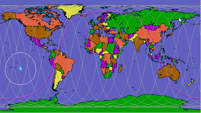
Figure 1: Aqua tracks over 24 hours. Note the light circle delineating the extent of the terrestrial horizon visible from Aqua at a certain instant in its orbit.
Figure 2 shows a view of South America, with the ALMA coordinates marked, and showing the full set of 16-days of ground track. For these orbital parameters, these represent ALL ground tracks from the satellite; the tracks repeat precisely every 16 days. As with Figure 1 & Figure 3, the ascending (S-N) orbits slant from lower right to upper left, while the descending (N-S) orbits slant from upper right to lower left.
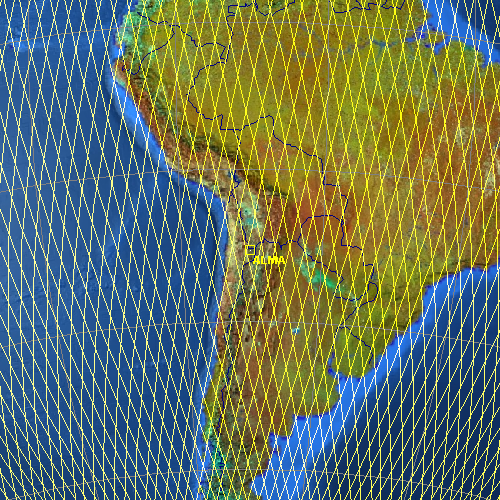
Figure 2. Ground tracks of Aqua over a full 16 day period, with the position of ALMA marked on a map of South America. Subsequent tracks repeat precisely every 16 days. The final CloudSat ground tracks will be similar, but not identical.
Figure 3 plots in more detail the ground tracks that pass close to ALMA over any 16-day period.
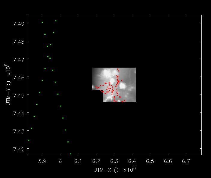
Figure 3. Ground tracks of Aqua: the green dots to the left mark the closest approach of Aqua ground tracks to the ALMA array; these marks are separated by one second of time along the Aqua orbit, although the radar transmission is of course continuous. The central red dots mark antenna positions in the extended ALMA configuration. The axes tick labels show UTM coordinates, with ticks every 10 km. The ground track of Aqua approaches within ~30 km of the center of ALMA. Of the two ground tracks shown, one is ascending (S-N) and the other descending (N-S). These 2 tracks are separated in time by about 8 days, but both repeat every 16 days.
These orbital tracks are to be regarded (August 2004) as representative; the final CloudSat orbit ground track could pass closer to or further away from ALMA.
Figure 4 plots the azimuth and elevation of all satellite tracks seen from ALMA, over a 16-day period.
Figure 4: Azimuth-elevation tracks of Aqua, seen at ALMA over a 16-day period. The satellite’s Azimuth and Elevation is marked for every 5 seconds of each satellite pass. The maximum elevation is less than 3 degrees from the zenith at the center of ALMA. Although this Aqua orbit may not correspond exactly to the final CloudSat orbit, the statistics of satellite positions will be very similar.
There is a receiver burnout risk, but this occurs only if the radar beam and the ALMA antenna beam are both pointing directly at each other. A simple calculation from first principles shows this to be a very unlikely event:
Suppose the radar paints two 5 km wide stripes down the earth every 90 minutes. This is 1/4000 of the near-equatorial earth every orbit, 0.004 of the earth every day. If these are random, a randomly located antenna on the earth expects only 1.5 illuminations per year. The motion of the satellite while it is illuminating the antenna will be about 25 arcminutes as viewed from the antenna. So if the antenna is looking within half an arcminute of that 15’ track at that time, the receiver will be lost. If we assume that an antenna has a uniform probability of pointing anywhere in the 10000 square degrees above 30 degs, there is a 7.10-7 chance of burnout per illumination. So the expected lifetime due to radar burnout is just under a million years, and the expected time before the first burnout for the 64-element ALMA, assuming ALMA antennas are pointed independently, is 15,000 years.
If this unlikely event were likely to harm personnel, it would be a serious matter. For “mere” property damage, amortizing the cost of destroyed receivers over 1,000,000 years would indicate that we should spend about $0.15 per year worrying about the problem – so the do-nothing option is quite supportable. Nevertheless, since a minor change of our operational policies can avoid even this small risk, we should NOT ignore the possibility.
The random-pointing calculation is modified because of the sun synchronous orbit of CloudSat, whose ground tracks repeat every 16 days. If none of the ALMA antenna pads are illuminated directly by the radar beam in any 16-day period, none will ever be. Conversely, if the CloudSat orbit is such that even once in 16 days any ALMA antenna pads are illuminated directly, then they will receive the same potentially damaging radiation EVERY 16 days. The orbit will be well known in advance, so we will know quite precisely the risk of receiver damage. If the AQUA orbit today is truly representative of the eventual CloudSat orbit, the closest that orbit comes to crossing the center of ALMA, within any 16-day period, is about 3 degrees of zenith distance, or a ground track distance of about 30 km – remember that the 14 km ALMA array subtends an angle of 1.2 degrees at the altitude of CloudSat. See Figure 3. However, the orbit will be slightly perturbed, and there are tolerances on the radar antenna pointing angle; if all factors conspired together, using the existing AQUA orbit, the CloudSat radar beam could just pass over the outer antennas of an ALMA 14-km configuration.
CloudSat over the ATF
Figure 5: The closest Aqua ground tracks with respect to the ATF over any 16 days. The closest approach is within 3 km of the ALMA antennas at the test site. The ground track is marked every second of time. The Aqua orbit used for these calculations may not be precisely the same as the final CloudSat orbit.
Although, using the current orbital parameters of Aqua, the satellite passes within about 30 km of directly over the center of ALMA, the situation for the ATF is much worse. Within any 16-day period, there is one pass almost directly overhead of the ATF antennas (i.e. within 3 km), and another orbit track that passes within 30 km. The 3 km pass puts the ATF antennas directly within the radar beam’s footprint. The 30 km pass is just at the limit of what could be considered dangerous for the ATF ALMA receivers. Figure 5 plots at 1 second intervals ground tracks that pass within 50 km of the ATF. Note that these calculations have used the current Aqua orbital parameters, so the final CloudSat orbit may be less unfavorable to the ATF than Figure 5.
Power received by an ALMA antenna and the implication for receiver survival
There are 4 classes of coupling between the CloudSat radar and ALMA antenna beams:
(1) Far antenna sidelobe to far sidelobe interaction. Assuming 0 dBi sidelobes for both the radar and the ALMA antennas, for 705 km spacing (the CloudSat orbital height) and 94 GHz, the propagation loss (between isotropic antennas) is 188.9 dB. For a transmitter (peak) power of 1.8 kW = 32.5 dBW, the power picked up in the receiving antenna is 32.5-188.9 = -156.4 dBW. Compare this with the system noise power in a receiver with bandwidth 4 GHz and T_sys = 20 K, which is k.T.B = 1.38x10-23 x 20 x 4 x 109 = 1.10x10⁻²⁰ W = -119.6 dBW. Thus the sidelobe-to-sidelobe peak signal is some 37 dB below the system noise in 4 GHz. Thus there is no receiver overloading, even for sidelobes somewhat above 0 dBi. Even precisely on the radar frequency, ALMA would barely detect the signal in this bandwidth.
(2) Main beam of the radar to far sidelobes of the ALMA antennas. The main beam gain of the radar antenna is given as 63 dB. The power picked up in the receiving antenna is:
(-188.9 + 32.5) + 63 = -93.4 dBW = -63.4 dBm.
(3) Sidelobes of the radar into the main beam of an ALMA antenna:
The main beam gain of a 12-m antenna at 94 GHz, assuming 70% aperture efficiency, is 80 dBi. The power picked up by this antenna pointing at 0 dBi sidelobes of the radar transmitting 32.5 dBW is: (-188.9 + 32.5) + 80 = -76.4 dBW = -48.4 dBm.
Compare these main beam-sidelobe and sidelobe-main beam coupling figures calculatated in (2) and (3) with the equivalent thermal noise in a 4 GHz receiver band, at the input to the receiver,
of -119.6 dBW, calculated in (1) above. In both cases, the received radar power is tens of dB greater than system noise. This is almost certain to cause saturation of the Band 3 ALMA receiver, meaning that useful observations will be impossible, but no physical damage will result. Because of the motion of the satellite (footprint velocity approx 7 km/sec), such interactions would last for less than one second for any single antenna, or about 2 sec if one considers the 14 km distribution of the large ALMA configuration.
(4) Main beam to main beam interaction. From figures used above, the power received is (to the nearest dB) (-188.9 + 32.5) + 63 + 80 = -13 dBW = 17 dBm = 50 mW. This is a harmful level for the receiver.
Tony Kerr provides a burnout figure of an SIS mixer of 1 mW per square micrometer of junction area. This is for DC power, and results from tests that were made a few years ago. Taking details of the band 3 mixer into account, Tony calculates that 60 mW of input results in 2 mW per sq. micrometer, i.e. just a factor of two above the burnout figure. Tony indicates that the burnout
level for pulsed power would depend on the thermal time constant of the junction, which is not known. The level for the 3.3 microsec pulses could be measured, but would not be trivial because a special Dewar setup allowing DC pulses to be injected would be necessary. Tony also points out that for band five and higher, the cutoff of the waveguide at the throat of the feed horn should provide protection from signals at 94 GHz.
Avoidance distances
1. Receiver damage. ALMA antennas should avoid pointing at the zenith when CloudSat is flying over. From the point of view of receiver survival, what avoidance distance is required between the ALMA antennas and CloudSat’s antenna beam? How close to the zenith is safe?
As shown above, the power received by an ALMA antenna with perfect main beam to main beam coupling is about twice the probable threshold for receiver damage. A slightly conservative goal would be to avoid receiving more than 10% of this threshold. Assuming the worst case of CloudSat flying directly over ALMA, this means that the ALMA antennas should be pointed off the zenith to give at least 13 dB attenuation with respect to their main beam. Sidelobes are assumed to be lower than -13 dB.
At 94.05 GHz a 12-meter dish has a 3 dB beamwidth (fwhp) of about 0.019 degrees, or +/-0.0093 degs. Assuming a Gaussian beamshape, the -13 dB point will be at +/-0.0193 degrees.
ALMA pointing uncertainty, or definition of “zenith,” should be less than 0.003 degrees
A bigger uncertainty is in the potential pointing error of CloudSat; the radar beam may deviate from the local gravitational vector by up to 0.07 degrees, with possible additional pointing error of 0.053 degrees. This gives an extra zenith avoidance margin of 0.053 + .07 = 0.123 degrees.
The satellite radar beamwidth, to first nulls, is +/-0.125 degrees.
Anomalous refraction: in principle, anomalous atmospheric conditions could bend the expected arrival direction of the 94 GHz radar signal by up to 0.01 degrees.
The ALMA receivers for different bands are all in the same focal plane, with a spread of far field pointing angle of nearly 0.4 degrees
Some antennas may have a nutating subreflector, which could move the beam by up to about 0.05 degrees.
ALMA itself extends of a range of +/-0.065 degrees in longitude and latitude, so allowing for ambiguities in whether each local antenna zenith angle is aligned with its own local gravity vector, to be safe we should add this uncertainty to the safety margin.
Adding all these margins (note a direct addition is used, not a quadratic addition) we reach a combined safety margin of ~+/-0.8 degrees. So, in the worst case even of CloudSat passing directly over ALMA, provided none of the antennas is pointing within 0.8 degrees of the zenith, we should be safe from receiver damage.
2. Interference. ALMA antennas should avoid pointing at CloudSat at any time when it is above the horizon, in order to avoid excessive interference. How far away from CloudSat is sufficient to reduce interference to tolerable levels?
I
n
the above calculation of power received by an ALMA antenna, with an
ALMA antenna main beam looking at CloudSat sidelobes, the received
power is -76.4 dBW, with receiver thermal power being -119.6 dBW;
i.e. CloudSat is (119.6-76.4) = 43 dB above receiver thermal noise in
the assumed bandwidth. Assuming observations are not being attempted
within the radar frequency band itself, by analogy with the ITU VLBI
interference criteria, the total interference power within the
receiver band should be kept below 1% of the thermal noise –
i.e. below -140 dBW. This requires an attenuation of 43+20 = 63 dB,
or for the ALMA antenna gain to be reduced from 80 dBi to 17 dBi.
From the ITU-R SA.509 model of the envelope of antenna sidelobes,
this is expected to occur about 4 degrees from the main beam;
however, that antenna model is only intended to be used from 1 - 30
GHz. From measurements on the IRAM 30-meter telescope at 39 GHz by
Dave Morris (Reference [4]) a safer offset for the 17 dBi gain radius
would be 10 degrees. So, in order to avoid excessive interference in
ALMA Band 3, away from the CloudSat frequency, the ALMA antennas
should come no closer than +/-10 degrees to CloudSat whenever the
radar is above the horizon.
Figure 6: The range of angular velocities of Aqua/Cloudsat seen from ALMA, as a function of satellite elevation angle. This enables the possible duration of interference to be calculated. At elevation angle 30 degrees, if the satellite passes close to the ALMA beam, interference could be expected for a duration of about 70 seconds.
If observations in Band 3 are in progress when CloudSat passes within 10 degrees of the ALMA field of view, the data should be flagged as bad. Figure 6 shows the range of satellite angular velocity seen from ALMA, in degrees/second, as a function of satellite elevation angle. This enables the likely duration of interference to be calculated for cases where the satellite passes close – i.e. within +/-10 degrees - to the ALMA beam. For an overhead satellite pass this period of interference could last up to about 30 seconds, while for the satellite passing near the ALMA beam at elevation 30 degrees, the interference could last about 70 seconds, and longer at even lower elevations.
Harmonics: the 2nd and 3rd harmonics (188.1 GHz & 282.15 GHz) of the CloudSat transmitter are given as 50 and 60 dB, respectively, down on the fundamental. The EIRP in the main beam is uncertain: in principle the 2nd harmonic boresight antenna gain could be 6 dB higher, and the 3rd harmonic 10 dB higher, than the fundamental, although it’s probably unlikely that the CloudSat antenna will be optimally illuminated at harmonic frequencies – more likely, the residual harmonic energy will be spread out into transmitter sidelobes. Provided that CloudSat is not within ALMA’s main antenna beam (or say, within 0.02 degrees) , interference from harmonics of CloudSat is only likely to be a problem precisely on the specific harmonic frequencies. The likelihood of ALMA pointing this close to the moving CloudSat in extremely small, and such interference would only be present in any single antenna for less than one second on a given satellite pass. Nevertheless, ALMA’s software should probably flag the occurrence.
Impact on ALMA
Here are the steps ALMA needs to take in order to avoid (a) damage to receivers, and (b) data corruption.
The ALMA antenna should never point within +/-0.8 degrees of the zenith. If this is ever necessary, say for maintenance or for transportation, then a protective shutter, or the solar attenuator, should be moved in place above the receiver feeds. If observations are needed within 0.8 degrees of the zenith, then the control software should check for the position of CloudSat before allowing tracking closer to the zenith.
Whenever ALMA antennas are pointed within 10 degrees of the CloudSat satellite, any data taken at least in Band 3 should automatically be flagged as bad. Harmonic interference is possible if CloudSat passes within 0.02 degrees of the ALMA field of view.
Observations within the frequency band 94.0 – 94.1 GHz should preferably be restricted to times when CloudSat is below the horizon.
Today’s estimate of the future CloudSat track has it passing essentially directly over the ATF, so for receiver protection there, precautions need to be taken as soon as CloudSat is launched in April 2005; however, the final CloudSat orbit may differ slightly from the current Aqua orbit, so the situation needs to be reassessed then.
Other similar projects
CloudSat is due to be launched in April 2005; although the mission lifetime is theoretically quoted as 20 months, the indications are that it will continue in operation for at least 3 years. There is a similar project currently being planned in Europe, with a launch date set for 2012, although details are not currently known. Unfortunately, it seems that interference of this type is becoming a fact of life now at mm wavelengths. ALMA needs to be able to deal with the situation.
ANATAC & other contributors
At the time this report was prepared, the ANATAC membership consisted of Barry Clark, Larry D’Addario, Darrel Emerson (chair), John Payne, Peter Napier, Dick Sramek, Art Symmes and Dick Thompson. The report was prepared with help from NRAO’s Spectrum Manager, Harvey Liszt. Mark Holdaway produced Figure 3.
Conclusions
The CloudSat mm-wave radar will be launched in April 2005; this may be the first of a series of mm-wave radars that ALMA will have to deal with. There is a finite chance of damage to ALMA receivers, which would occur if the radar beam and an ALMA antenna ever look directly at each other. However, such an occurrence would be quite rare, and simple precautions can avoid the danger altogether – in particular, if the ALMA antennas are never pointed within 0.8 degrees of their zenith without having receiver protection in place, or without control software first checking whether a CloudSat ground track is likely to pass close to ALMA.
Interference will be experienced within Band 3 whenever ALMA points within10 degrees of the satellite, through the far-out sidelobes of the radar beam; ALMA software should be capable of flagging such circumstances
References:
[1] Notes on the Proposed 94.5 GHz Space based Cloud Profiling Radar and its impact on mm-wave Radio Astronomy. John E.B. Ponsonby, Nuffield Radio Astronomy Laboratories, Jodrell Bank: November 1996.
See http://www.alma.nrao.edu/memos/html-memos/alma504/0228_001.pdf .
[2] The CloudSat Mission and the A-Train, A new Dimension of Space-Based Observations of Clouds and Precipation, Graeme L. Stephens et al., Bulletin of the American Meterorological Society, Vol 83 Number 12, December 2002, 1771-1790. A copy can be found at: http://ams.allenpress.com/pdfserv/i1520-0477-083-12-1771.pdf
[3] The latest set of NORAD orbital elements for Aqua, and presumably in future for CloudSat itself, can be obtained from http://celestrak.com/index.shtml , via NORAD Two-Line Element Sets, Current Data, Weather & Earth Resources Satellites, Earth Resources.
[4] Interference and Sidelobe Levels of Millimeter Wavelength Radiotelescopes, by Dave Morris, IRAM, France. ITU-R Documents 7D/16-E and 7B/8, 23 February 1998. A copy of this can be found at http://www.alma.nrao.edu/memos/html-memos/alma504/mmsidelobes.pdf .
[5] Orbit and Transmit Characteristics of the CloudSat Cloud Profiling Radar (CPR), JPL Document No.D-29695, Jet Propulsion Laboratory, California Institute of Technology, Pasadena, CA 91109. Prepared by S. Durden and R. Boain, 26 July 2004. A copy of this can be found at http://www.alma.nrao.edu/memos/html-memos/alma504/CloudSat-Scrubbed.pdf .
Tags: cloudsat radar, the cloudsat, implications, cloudsat, radar
- EK4 ÖRNEK TC AFYON KOCATEPE ÜNİVERSİTESİ REKTÖRLÜK BİNASI ACİL
- HOTARAREA GUVERNULUI NR 1612 DIN 20 NOIEMBRIE 2006 PRIVIND
- CHROMATOGRAPHY OF PHOTOSYNTHETIC PIGMENTS STUDENTS’ SHEET INTRODUCTION THE
- 1 2 3 4 PROGRAMA DE LA ASIGNATURA “SEMINARIO
- REQUEST FOR PRODUCT CERTIFICATION IMPORTANT THIS FORM SHOULD BE
- LISTE DES ÉTABLISSEMENTS DE LA COMMUNAUTÉ FRANÇAISE NOM PRÉNOM
- ŽIVOTOPISNÁ POZNÁMKA NEELA WINKELMANN – HEYROVSKÁ NAR 1969 V
- RESOLUCIÓN DE 9 DE MARZO DE 2015 DE LA
- 7 NO STEP PRIVATE PROPERTY ATTENTION! ELECTROMAGNETIC FIELD BASE
- MINISTERIO DE SALUD CONSEJO NACIONAL DE SEGURIDAD SOCIAL EN
- SZAKMAI MEGÚJULÁS A SZENTESI KÖZOKTATÁSI INTÉZMÉNYEKBEN TÁMOP 31408220090029 JÁTÉKOS
- INTRODUCCIÓN EL USO DE SUPLEMENTOS DEPORTIVOS ESTÁ AMPLIAMENTE EXTENDIDO
- JUZGADO PRIMERA INSTANCIA Nº DE PROCEDIMIENTO JUICIO
- INTRODUCTORY INFORMATION ON KEEP NORTHERN IRELAND BEAUTIFUL KEEP NORTHERN
- SELFEMPLOYMENT FOR DISABLED PEOPLE WORK FOR YOURSELF 1 DEMAND
- E252 CLEAPSS FONT MARCH 2007 STRICTLY CONFIDENTIAL CIRCULATE TO
- PRESS RELEASE A LAW REFORM COMMISSION REPORT WHICH CONTAINS
- NA PODLAGI 17 IN 21 ČLENA ZAKONA O ŠPORTU
- REPRISE P4A PISTA 20 X 40 M O 20
- A3512 PAGE 3 WIPO E A3512 ORIGINAL ENGLISH DATE
- SHORT TITLSHORT TITLE CASE NUMBER AFFIRMATIVE DEFENSES – ATTACHMENT
- THE UNIVERSITY OF NORTH CAROLINA WOMEN’S SOCCER TEAM’S CORE
- A LA ILMA SRA DEFENSORA DEL PUEBLO DON LUIS
- WEB SERVICE DE RECINTOS FISCALIZADOS V10625 MARZO2006 MANUAL DE
- K A R T O T E K A
- CHAPTER 7 FAILUREPRONE PRODUCTION LINES ??? DUE IN ???
- PROJECT NO RIGHT OF ENTRY AGREEMENT THIS RIGHT
- 8 UNITED NATIONS ECONOMIC COMMISSION FOR EUROPE SCIENTIFICRESEARCH CENTRE
- PERFECT READINGS IN RUSSIAN 357 PERFECT READINGS IN RUSSIAN
- November 2007 21070335000000 Project Ieee 80221 Mihs httpwwwieee802org21 Title
VIJESTI ODRŽANI TURNIRI U GOLFU I TENISU UDRUGA HRVATSKIH
PLANIFICACIÓN EJECUCIÓN Y EVALUACIÓN DE LOS PLANES DE SALUD
 STUDENTI GENERACIJE 08 I MLAĐI STUDENTI GENERACIJE 08 I
ZASADY AKTUALIZACJI DANYCH ZAWARTYCH W EWIDENCJI GRUNTÓW I BUDYNKÓW
 RAPORT Z EWALUACJI WEWNĘTRZNEJ MIEJSKIEGO PRZEDSZKOLA NR 85 W
OPĆINA BOSILJEVO BOSILJEVO 14 47251 BOSILJEVO DOKUMENTACIJA ZA NADMETANJE
THE PARKESMITNRAO (PMN) SURVEYS VIII SOURCE CATALOG FOR
WASHINGTON DC LAW OFFICES OF ROMNEY WRIGHT EASTERN SHORE
 PCTAXIX2 PAGE 6 WIPO E PCTAXIX2 ORIGINAL ENGLISH DATE
 ANEXO IV ROTEIRO PARA PREENCHIMENTO O IMPRESSO PADRONIZADO DE
ESBORRANY ACTA DE LA SESSIÓ ORDINÀRIA DEL PLE DE
 CHARLES DARWIN EL ORIGEN DE LAS ESPECIES PRÓLOGO
  ONTARIO COLLEGE OF SOCIAL WORKERS AND SOCIAL SERVICE WORKERS
 APPLICATION FOR HEAVY VEHICLE PARKING PERMIT 1 YOUR DETAILS
PROCEDEMENTO A SEGUIR NO LUGAR DA PALABRA ¿QUÉ É
 S AMWONTECH 东莞市科文试验设备有限公司 HTTPWWWKOWINTESTCOM 温湿度程式控制器 PROGRAMMABLE TEMPERATURE & HUMIDITY
HOUSES OF WORSHIP APOSTOLIC ST DAVID ARMENIAN CHURCH 2300
 RAPORT Z BADANIA ANKIETOWEGO MIESZKAŃCÓW OLSZTYNA ZAMAWIAJĄCY GMINA OLSZTYN
 DEAS 1352019 ICS 7714065 HS 7217120000 DRAFT EAST AFRICAN
 13 Lengua Castellana y Literatura 2º de Bachillerato Tema
