ATTACHMENT 1 ILLUSTRATION OF THE DRAFT TEST PROCEDURE
TRANSLATION ATTACHMENT 1 DETAILS OF MANAGEMENT AND(ATTACHMENT 1) LAKEVIEW HEALTH CENTER VOLUNTEER INFORMATION SHEET NAME
(ATTACHMENT A) EUROPASS CURRICULUM VITAE INSERT PHOTOGRAPH REMOVE HEADING
(FACILITY NAME) EMERGENCY OPERATIONS PLAN ANNEX C EVACUATION ATTACHMENT
(RD GUIDE 19 ATTACHMENT 7) RD INSTRUCTION 1942A
(RD GUIDE 19 ATTACHMENT 8) FMHA INSTRUCTION 1942A
歩行者保護基準案検討内容一覧
Attachment 1
Illustration of the draft test procedure
Attachment 2
P rocedure
to determine the test area
rocedure
to determine the test area
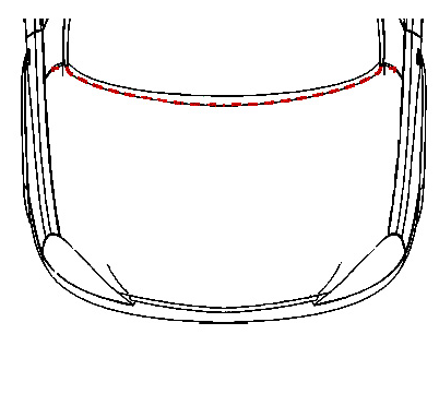
The test area should be the area surrounded by the front test line, rear test line and side test lines.
Front test line:
The rear side line was chosen out of two lines to be assigned to the front test line. One line was the line where WAD was 1,000mm. The other line was located 165mm backward from the Bonnet Leading Edge Reference line.
Rear test line:
The front side line was chosen out of two lines to be assigned to the rear test line. One line was the line where WAD was 2,100mm. The other line was located 82.5mm forward from the line where the impactor contacted the bonnet when the impactor contacted both the windscreen and bonnet, assuming that both the wiper arms and other equipment are removed.
Side test line:
The lines are located 82.5mm inside from the Bonnet Side Reference line.
Ground Reference Plane
A horizontal plane that passes through all tire contact points of a vehicle while the vehicle is in its normal ride state. (See Figure 1.)
F igure
1: Ground Reference Plane
igure
1: Ground Reference Plane

W
W AD
(Wrap-Around Distance) is the geometrically
traced distance from the contact point with the Ground Reference
Plane, vertically below the front face of the bumper, to any point on
the vehicle front structure. (See Figure 2.)
AD
(Wrap-Around Distance) is the geometrically
traced distance from the contact point with the Ground Reference
Plane, vertically below the front face of the bumper, to any point on
the vehicle front structure. (See Figure 2.)
WAD
Figure
2 : WAD
Bonnet Side Reference line
T he
geometric trace of the highest points of contact between a straight
edge, held parallel to the lateral vertical plane of the vehicle and
inclined 45 deg. is traversed down the side of the front structure,
and the side of the front structure.
he
geometric trace of the highest points of contact between a straight
edge, held parallel to the lateral vertical plane of the vehicle and
inclined 45 deg. is traversed down the side of the front structure,
and the side of the front structure.
Bonnet
Side Reference line
Figure 3 : Bonnet Side Reference line
Bonnet Leading Edge (BLE) Reference line
The geometric trace of the highest points of contact between the straight edge that is held parallel to the vertical fore and aft planes of the vehicle with 1m length, the bottom point is 600mm above the Ground Reference Plane, and inclined 50 deg. is traversed down the front of the front structure, and the front of the front structure.
In the cases described below, the line will be determined by the respective method given:
In the case that the straight edge is parallel with the vehicle front structure:
The angle of the straight edge should be changed to 40 deg. (See Figure 4-3.)
In the case that the top point of the straight edge contacts the vehicle front structure:
The BLE Reference line should be the line where WAD is 1000mm. (See Figure 4-4.)
In the case that the straight edge contacts the bumper:
The BLE Reference line should be determined without the bumper. (See Figure 4-5.)


0 ATTACHMENT 3 INTERNATIONAL CIVIL AVIATION ORGANIZATION AERONAUTICAL MOBILE
08-ADM-12-Attachment-9-Agreement-to-Modify-Order-of-Support-andor-Compromise-Arrears-shd
112011 CP&PIXF1300 ATTACHMENT MAINTAINING THE CHECK LEDGER TO
Tags: attachment 1, ======================================== attachment, illustration, attachment, draft, procedure
- UTSA EVENTS MANAGEMENT & CONFERENCE SERVICES TO USE CHECKLIST
- FORMULARIO DE RESPONSABILIDAD CAMPOENATO ESPAÑA Y ANDALUZ T850 GRAN
- ZAŁĄCZNIK DO NR 2 DO REGULAMINU FORMULARZ ZGŁOSZENIOWY DOTYCZĄCY
- PERSONAL QUE EN EL AÑO 1957 TRABAJABA EN LA
- SPS STRATEGY ON THE MANAGEMENT OF DRUG MISUSE PATHWAYS
- GYVENIMO AIDAS 10 NR ŠVENTINIS PRIEDAS K ŪČIŲ
- PELÍCULA “LA OLA” TÍTULO ORIGINAL DIE WELLE ( 2008)
- E NERGY (BTU) MEASUREMENT SYSTEM SPECIFICATION FOR CENTRAL
- 8ABRIL2013 CORREO ELECTRÓNICO DE DIVISIÓN DE FORMACIÓN Y PERFECCIONAMIENTO
- DEPARTAMENTO LENGUA CASTELLANA Y LITERATURA PALOMA RUIZ LENGUA CASTELLANA
- CARE RECEIVER APPLICATION 616 AMERICA AVE SUITE 170 BEMIDJI
- KIELTENOPETTAJAN TYÖKALUPAKKI LAUSEELABOROINTIA PERUSOPETUKSESSA ALAKOULULAISTEN KANSSA SALLA SIMONEN 410088
- ALPHABETICAL GUIDE TO PRESCRIPTION ENDORSEMENT FOR PHARMACY CONTRACTORS QUICK
- POST PRINT VERSION OF MR RUTGERS (2010) THE OATH
- 150 PANJAB UNIVERSITY CHANDIGARH160014 (INDIA) (ESTD UNDER PANJAB UNIVERSITY
- APROVAT PEL PLE DE DATA 2022015 LA SECRETÀRIA PLEC
- SUBDIRECCIÓN GENERAL DE PROSPECTIVA Y COORDINACIÓN DE PROGRAMAS MEMORIA
- PROJECTE D’ETAPA DE L’ÀREA DE LLENGÜES ESTRANGERES ANGLÈSFAIRYLAND PROJECTE
- TEMATY USTNYCH PREZENTACJI MATURALNYCH Z JĘZYKA POLSKIEGO W SESJI
- MINISTERIO DE CIENCIA E INNOVACIÓN SUBDIRECCIÓN GENERAL DE PROSPECTIVA
- LOS VERBOS REGULARES E IRREGULARES MAS IMPORTANTES EN EL
- D EVELOPING CORE VALUES I OUTLINE A WHAT ARE
- JORD & AFFALD REF OKI DEN 16 APRIL 2010
- NA TEMELJU ČLANKA 51 I 52 ZAKONA O AUTORSKOM
- GODEVIL MANUFACTURERS OF LOUISIANA INC 18649 WOMACK ROAD
- LIST OF ITEMS REQUESTED TO BE AVAILABLE ON SITE
- ERMENİ SORUNU İDDİALAR GERÇEKLER TÜRK ERMENİ İLİŞKİLERİ
- 8TH MEETING EUROPEAN NETWORK OF MEDICAL COMPETENT AUTHORITIES RECOMMENDED
- MĚSTSKÝ ÚŘAD NÝRSKO EVIDENCE OBYVATEL NÁMĚSTÍ 122 340 22
- 8 PROSPECTIVA Y PLANEACIÓN ANTONIO ALONSO CONCHEIRO ANALÍTICA CONSULTORES
BO LA BASE DE EVIDENCIA CLÍNICA DE LA HOMEOPATÍA
 UNAOC PARTNERS FORUM ISTANBUL TURKEY MAY 31JUNE 1 2012
LISTA OSÓB UPRAWNIONYCH DO PROWADZENIA SZKOLEŃ REALIZATORÓW PROGRAMU DOMOWYCH
PROGRAMA DE INGLES AÑO 4º CICLO ESCOLAR 2012
 APPENDIX B INTERNAL PROCEDURE TO BE FOLLOWED WHEN APPLYING
USAID PROCUREMENT INFORMATION BULLETIN PIB NO 15006 FOR ULTRASOUND
CURRICULUM VITAE NIMI HENNA PAASONEN SYNTYMÄVUOSI 1972 SYNTYMÄPAIKKA HYVINKÄÄ
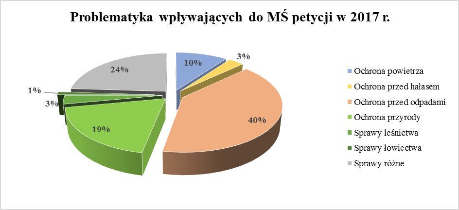 ZBIORCZA INFORMACJA O PETYCJACH ROZPATRZONYCH W MINISTERSTWIE ŚRODOWISKA W
 INTERNAL ASSESSMENT RESOURCE MEDIA STUDIES 36B FOR ACHIEVEMENT STANDARD
EULAC JOINT INITIATIVE FOR RESEARCH AND INNOVATION 16 AND
LABORATORIO DE PATOLOGIA VETERINARIA URQUIZA 3746 TEL 0341
CUESIONARIO DE PLANIFICACION DE PATRIMONIO CONFIDENCIAL NOMBRE DE CLIENTE
 BARTEK MODZELEWSKI VOCABULARY 1 DOPASUJ PODPISY DO OBRAZKÓW WPISZ
WZORY DOKUMENTÓW POTRZEBNE NA SPRAWOZDAWCZO WYBORCZY ZJAZD REGIONALNY OZZL
 Speech11219 Viviane Reding Vicepresident of the European Commission eu
埃及政府指定接待中国旅游团的旅行社名单 (233家) 序号 旅行社名称 地址 联系方式 1 3 A
SPOJENÁ ŠKOLA J KRÁĽA 39 ZLATÉ MORAVCE VÝSLEDKY 12
HEALTH AND SAFETY POLICY THIS IS THE STATEMENT
 KARTA USŁUG NR 2WGKKIN D NAZWA USŁUGI PRZEKSZTAŁCENIE PRAWA
 1 AIRCRAFT MAINTENANCE EXPERIENCE SAMPLE TASKS APPLICANT NAME
