ROCK HOGROCK DRILLING PRODUCTS RH5RC DTH RECIRCULATION HAMMER OPERATION
ROCK HOGROCK DRILLING PRODUCTS RH5RC DTH RECIRCULATION HAMMER OPERATION

Rock HogRock Drilling Products
RH5RC
DTH ReCIRCULATION HAMMER
OPERATION & MAINTENANCE MANUAL
MANUAL No HW-49020
Web Site @ www.rockhog.com
E-Mail Address: [email protected]
Table of Contents
Section 1. General Information 2
2.1 Lubrication of Internal Parts 3
Section 1. General Information
1.1 Description
The RH5RC hammer is a valveless, pneumatic percussion, reverse circulation hammer for drilling in all rock formations. It is designed for exploration applications that utilize double-wall pipe to collect the ejected sample, known as RC drilling. The hammer incorporates one moving part, the piston, making the hammer very reliable. The sample tube is a one-piece tube that can be pulled out without having to break the hammer. All external parts are hardened to resist wear while all critical internal parts are also hardened for maximum service life. The simple design also makes the hammer easy to maintain and service.
1.2 Specifications
1.3 Air Supply
A minimum of 250 cfm should be supplied to the hammer. The hammer will function on lower supplies but the penetration rate will be very slow. Keep in mind that even though the hammer will run on these low air volumes, the RC process may not. Make sure the air supply is sufficient for collecting the cuttings.
For the fastest possible penetration, the hammer should be operated at the highest obtainable pressure for the given air supply. A maximum pressure of 350 psi is recommended. Operating at pressures over 350 psi will increase penetration rates but shorten the service life of internal hammer parts and the bits.
The following chart shows the hammers operating pressure for a given air volume supply based on operation at sea level. Again, the hammer will operate at pressures over 350psi but the service life of the internal parts will be reduced.
1.4 Unpacking a New Hammer
First make note of the hammer Part Number & Serial Number found on the ID label outside on the hammer shipping tube and also on the ID label on the wearsleeve of the hammer. Your Rock Hog representative will need these numbers if you have questions on the hammer. The 12-digit hammer serial number is the backhead & air distributor numbers put together.
Section 2. Hammer Operation
2.1 Lubrication of Internal Parts
The hammer must have a constant and adequate supply of oil to prevent part wear, corrosion, and failure. Rock Hog recommends Exxon AROX EP series, Chevron VISTAC series or an equivalent grade. Contact your local lubricant representative for the proper grade to use for your drilling environment and temperatures.
Make sure the oil injector is filled and working properly. Always verify that there is oil coming through the drill string, DO NOT RUN THE HAMMER WITHOUT CONSTANT OIL INJECTION!
Set the system to inject 1 pint per hour for every 300 cfm of air supply. Example, if the supply is 950 cfm, inject 950/300 or 3.2 pints per hour.

2.2 Lubrication of Threaded Connections
All threaded connection must be coated with a no-gall grease. Both the backhead and chuck thread into the wear sleeve. The hammer is shipped with grease on both these connections. All drill pipe connections must also be coated. When applying grease, be careful not to put grease where it will enter the air stream. The grease will not blow through the hammer but stick to the internal parts. Excessive grease in the hammer will close the airways and stop the hammer.
Use a high performance copper based grease. Rock Hog recommends its own Rock Hog Thread Grease. Ask your Rock Hog representative for part number 350010.
2.3 Hole Cleaning
The up-center-tube velocity will always be more than sufficient even with a small air supply. Just be aware that if the shroud wears and develops too much leakage past it, the sample size will become smaller due to air being lost around the shroud and the tube may begin to clog.
2.4 Setting the Choke
This hammer currently does not have a choke incorporated into the hammer. If excess air needs bled off use a venturi sub in the drill string. Your local pipe supplier should be able to assist with this.
2.5 Effect of Elevation
Elevation above sea level affects the compressor output. As elevation increases, the compressor’s volume output decreases. Use the table below to determine volume loss.

2.6 Water Injection
Injecting water into the air supply is a common practice to keep down dust and to improve hole cleaning in soft formations. ALWAYS USE A CLEAN SUPPLY OF WATER.
Water injection will increase the hammer operating pressure and reduce the service life of the internal parts. Therefore, use just enough water for the drilling conditions present.
When drilling is complete, always shut off the water and blow air and oil through the drill string to remove the water and coat internal surfaces with oil. This will help prevent surface corrosion of the steel.
2.7 Drilling Under Water
The hammer is equipped with a check valve that closes when the air supply is shut off. This maintains air pressure inside the hammer and prevents water from coming up into the hammer.
Drilling under water increases the backpressure. The higher the head of water the greater the backpressure, the slower the hammer will penetrate. A point can be reached where the up-hole velocity is insufficient to overcome the water head and the piston will stop.
2.8 Drill Pipe
Drill pipe must be kept clean and straight. Dirt and rust blown out of the drill pipe and into the hammer will damage the hammer’s internal parts. Always cover the hole in the drill pipe when doing a pipe change. Always blow out the pipe before connecting it to the drill string.
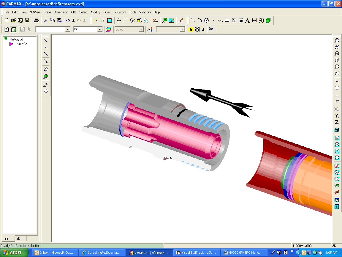
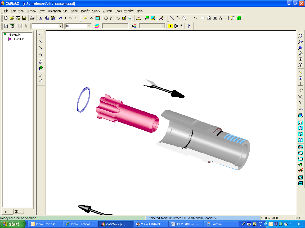
2.9 Connect the Hammer
First make sure any o-rings needed to seal the sample tube to the drill pipe tube are present and in good condition. Next, make sure the center tube will fit properly to the drill pipe tube. If needed, pull the center tube out and try it on the pipe tube.
Hoist the hammer to the rig. If the hammer is new, pour about a pint of rock drill oil down around the center tube in the backhead. Connect to the drill string. If the hammer is new, see section 2.10 on how to install the bit. Once the bit is in the hammer, check to make sure the backhead and chuck are tight. If needed tighten both the chuck and backhead before starting the hammer. When tight, there should be no gap between the chuck & sleeve shoulders and between the backhead & sleeve shoulders. ALWAYS USE A WRAP-AROUND WRENCH TO GRIP THE WEAR SLEEVE.
Once the hammer is connected, check the travel of the bit. In the drilling position, the bit should shoulder on the chuck and when the hammer is pulled up, the bit should drop out 1” (25mm).
2.10 Installing the Bit
The best place to install the bit is when the hammer is mounted on the rig. Turn the chuck out. The bit retainer ring will be setting in the top of the chuck. Set both halves of the ring to the side. Apply a coating of no-gall grease to the bit splines. Set the chuck down over the bit shank. Put the two halves of the ring back into the chuck. Set the shroud (the shroud diameter must be matched to the bit, normally the shroud is about .06” (1.5mm) smaller than the bit) down over the bit/chuck. Turn the shroud until its square drive drops onto and locks with the chuck’s square drive. Coat the threads with no-gall grease. Thread the chuck back into the wear sleeve. The shroud will seat right onto the sleeve. There should be no gap.

Note that the shroud diameter controls the sample size. The smaller the shroud, the more material will be blown back up the hole instead of the center tube. However, if the shroud is too big it will bind in the hole.
2.11 Drilling
With the hammer/bit up off the bottom of the hole, supply air to the hammer. The air will blow through the hammer but the piston will not cycle. This allows for continuous blowing to clean out the hole when needed.
Start rotation of the drill string and lower the hammer/bit onto the bottom of the hole. As the bit pushes into the hammer, the piston will begin to cycle and the pressure will build to its normal operating level.
Once a consistent formation is being drilled, set the rotation speed and hold down pressure. As a starting point, use a rotation speed in revolutions per minute (RPM) of:
RPM = 154 / bit size (in inches)
Set the hold down weight on the bit. As a starting point, the weight should be 2000 lb to 3000 lb. Keep in mind that as the hole goes deeper, the weight on the bit increases. Eventually hold back is needed to keep excessive weight off the bit.
Only driller experience will determine what RPM and bit weight combination work best in a given formation. In general, too slow a RPM results in slow penetration and shortened bit life but too fast a RPM will also shorten bit life. Excessive weight on the bit will cause bit button failure. Insufficient weight causes the piston blow energy to be dissipated into the bit and piston, which will lead to steel failure of these parts.
Make sure to clear the entire center pipe of cuttings before doing a pipe change.
2.12 The Drill Bit & Shroud
The bit and shroud for this hammer are proprietary to Rock Hog. You will need to purchase both bits and shrouds from your Rock Hog representative. Sizes of 5-1/4”, 5-3/8”, 5-1/2”, 5-5/8”, 5-3/4” are available.
The bit is what carries the hammer piston energy to the rock therefore the condition the bit cutting face should be checked after the completion of each hole drilled.
As the bit accumulates drill time, the bit’s buttons and steel and the shroud will start to wear away. The wear pattern and rate of wear will vary greatly depending on the formation being drilled and drill settings.
In soft formations such as limestone where the bit wears slowly, watch the buttons for “snakeskin” on the surface. These surface cracks must be ground off to prevent button failure.
In hard formations where the bit wears quickly, watch the size of the flats on the buttons. The buttons should be sharpened when the width of the flat is no wider than ½ the diameter to help prevent bit failure.
Some formations wash the steel away quickly. In this case the buttons start to protrude excessively. The buttons need to be ground down to prevent them from breaking off.
Dull buttons are the single biggest contributor to slowed penetration and excessive stress to the bit and hammer.
If a bit must be changed before a hole is complete, make sure the gage diameter of the bit and shroud used to complete the hole is no larger than the bit and shroud just removed. Using a larger bit and shroud will result in probable lost of the gage buttons or binding before the bit reaches the bottom of the hole. For this reason, always keep 1 or 2 worn bits and shrouds that are in good condition on the drill rig.
When installing a new bit make sure the shroud used has the correct outer diameter, normally about .06” (1.5mm) smaller than the bit. Rock Hog recommends always putting a new shroud on a new bit.
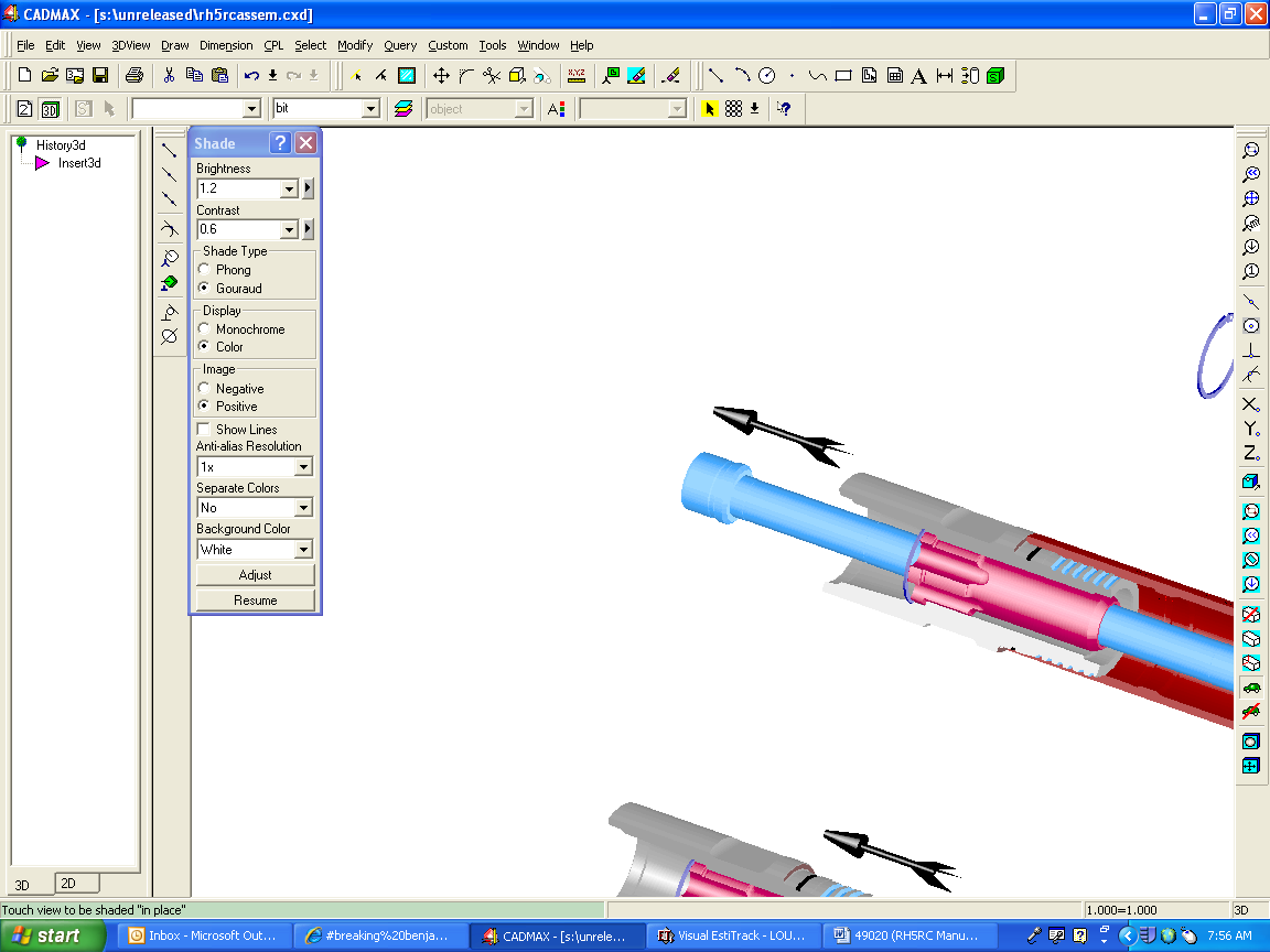
2.13 Breaking Threads Loose
When breaking the chuck thread loose to change bits, or the backhead loose to do hammer maintenance, follow these guidelines:
ALWAYS USE A WRAP-AROUND WRENCH this is to prevent pinching the sleeve out-of-round
KEEP SHARP JAWS IN THE WRENCH the wear sleeve is very hard to give a long service life so only quality hardened or diamond-tipped jaws in good condition will grip the sleeve
DO NOT WELD ON THE SLEEVE welding on the hardened sleeve will crack the sleeve and voids any warranty on the sleeve.
PLACE THE WRENCH AS SHOWN BELOW
Caution: When breaking and removing the drill pipe from the hammer, watch the hammer’s center tube. It may stick to the drill pipe tube and come out of the hammer when the pipe is pulled off.
2.14 Monitoring
As the hammer accumulates drill time, these areas need to be monitored to determine when to service the hammer.
External surfaces: Rock Hog hammer parts are made from the best materials and hardened for long life but eventually these surfaces will wear away. The rate of wear depends on the formation being drilled, drilling speed and airflow. Make periodic checks to know what condition the parts are in.
Check the bit and shroud after every hole. Watch that the bit gage does not wear below the shroud diameter. If this occurs the shroud will bind in the hole. Shrouds should not be used once the outside has worn down to 4.9” (124mm). Watch that the shroud does not wear to far below the size of the bit. This will begin to reduce the quality of the sample and possibly cause clogging in the center pipe.
Check the outside of the wear sleeve. If one end is wearing more than the other, flip the sleeve when the smaller end wears down to 4-7/16” (113mm). This will give additional sleeve life. Once any location on the sleeve wears down to a 4-1/4” (108mm) diameter, replace the sleeve.
Center exhaust tube: check the center exhaust tube end wear frequently. The bit end of the tube will wear back. The tube can wear back 2.5” (60mm) before replacement is needed. With the chuck removed from the hammer, measure from the wear sleeve face to the end of the tube. Replace the tube if the end of the tube measures more than 6.2” (160mm) back from the wear sleeve. If this length is being checked when the hammer is not attached to the drill pipe, make sure the tube is seated down against the adapter tube in the backhead before checking.
Chuck splines: check the condition of the chuck splines each time the bit is removed. Do not put a chuck with badly worn splines on a new bit.
Shoulder Gap: a hand-tight backhead will not be seated on the sleeve. Once the backhead is torqued down, this gap will close and the backhead will seat on the sleeve. This clamps the internal parts to prevent part movement. Periodically check the gap between the sleeve and hand-tight backhead. If the gap falls below .08” (2.0mm), refer to Section 3.4-step 8.
Operating pressure: this is the best way to know what condition the internal parts are in. As internal parts wear, the operating pressure, and therefore the penetration rate, will drop. Only the operator can say when hammer performance has dropped below an acceptable level at which time the hammer must be serviced. If the pressure goes up after the hammer has been in service for some time, this would indicate the piston is sticking or the air passages inside the hammer are becoming restricted.
2.15 Storage
Overnight
When drilling is complete for the day, shut off water and any other injections except the oil and allow air and oil only to blow through the hammer for a minute or two. This will blow out most of the water and other injections and coat all the internal parts with oil. If the hammer is in a wet hole, bring the hammer above the water level before blowing it out.
Short term
If the hammer will be off the rig for no more than 3 weeks, blow air and oil only through the hammer for a minute or two before taking it off the rig. This will blow out most of the water and other injections and coat all the internal parts with oil. Store that hammer in a dry area with the ends covered. The storage area should have a steady temperature to prevent surface condensation during temperature swings.
Long term
A used hammer going into storage for a month or more should be torn down with all parts cleaned, dried, oiled and stored assembled or disassembled in a dry, steady temperature area. This is to prevent surface corrosion. Surface corrosion is a main cause of part failure in hammers.
Section 3. Maintenance
3.1 Schedule
If the need for service defined in Monitoring, section 2.14, is not reached first, follow these guidelines for servicing the hammer:
When the hammer is operated to the parameters defined in section 2 in formations up to what is considered “hard”, perform service every 25000 feet (7600 meters) of drilling.
When water injection & drilling foams are used extensively, perform service every 18000 feet (5500 meters).
When drilling in “very hard” formations or when drilling under heavy mud, perform service every 10000 feet (3000 meters)
When injecting agents that are corrosive to metal, like potash to coat the hole wall, tear down and clean the hammer at completion of the job.
Use this as a starting point. Keep a log of service done-vs.-footage drilled. This will help refine the service schedule to fit your operation.
3.2 Disassembly
All parts are a sliding or clearance fit inside the hammer but may be tight inside the hammer depending on the condition of the parts and the time period since the hammer was last serviced. There are a few steps that require a bar be used to push/drive on parts. Always use a non-hardened steel bar. Wood can splinter and chip leaving contaminants in the hammer.
1. Break both the backhead and chuck threads loose. See section 2.13
2. Lay hammer on a bench, mark the sleeve ends “backhead” and “chuck”
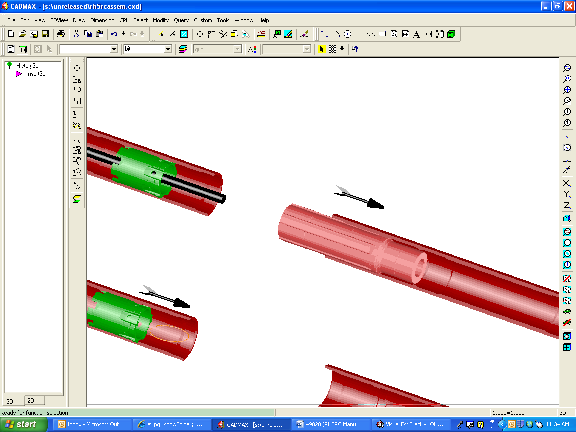
3. Pull out the center tube. If needed there are threads on the top of the tube to put a puller on. On the Remet tube a 2-1/2” pipe coupler thread will fit. On the Metzke a 2” pipe coupler thread will fit. The coupler bore may need opened up slightly to fit over the Metzke tube.
Do not beat on the bottom of the tube to remove it. The worn end is sharp and thin. Beating on the end will distort the end and when the tube is pulled out it will cut o-ring seals and/or also get stuck in other parts. Always pull from the top. A puller is available from Rock Hog for pulling the tube if needed. Ask you Rock Hog representative for p/n 45413.
If the backhead is being removed, an optional way to remove the center tube is to leave the tube in and thread out the backhead. The tube will come out with the backhead. Then the tube can be pushed out of the backhead.
Note: When breaking and removing the drill pipe from the hammer, the tube may stick to the pipe and come out of the hammer when the pipe is pulled off.
4. Turn out the backhead. The adapter tube is retained inside the backhead by a snap ring. The tube does not need removed from the backhead unless required. Make sure to check inside the tube on the bottom for the o-ring.
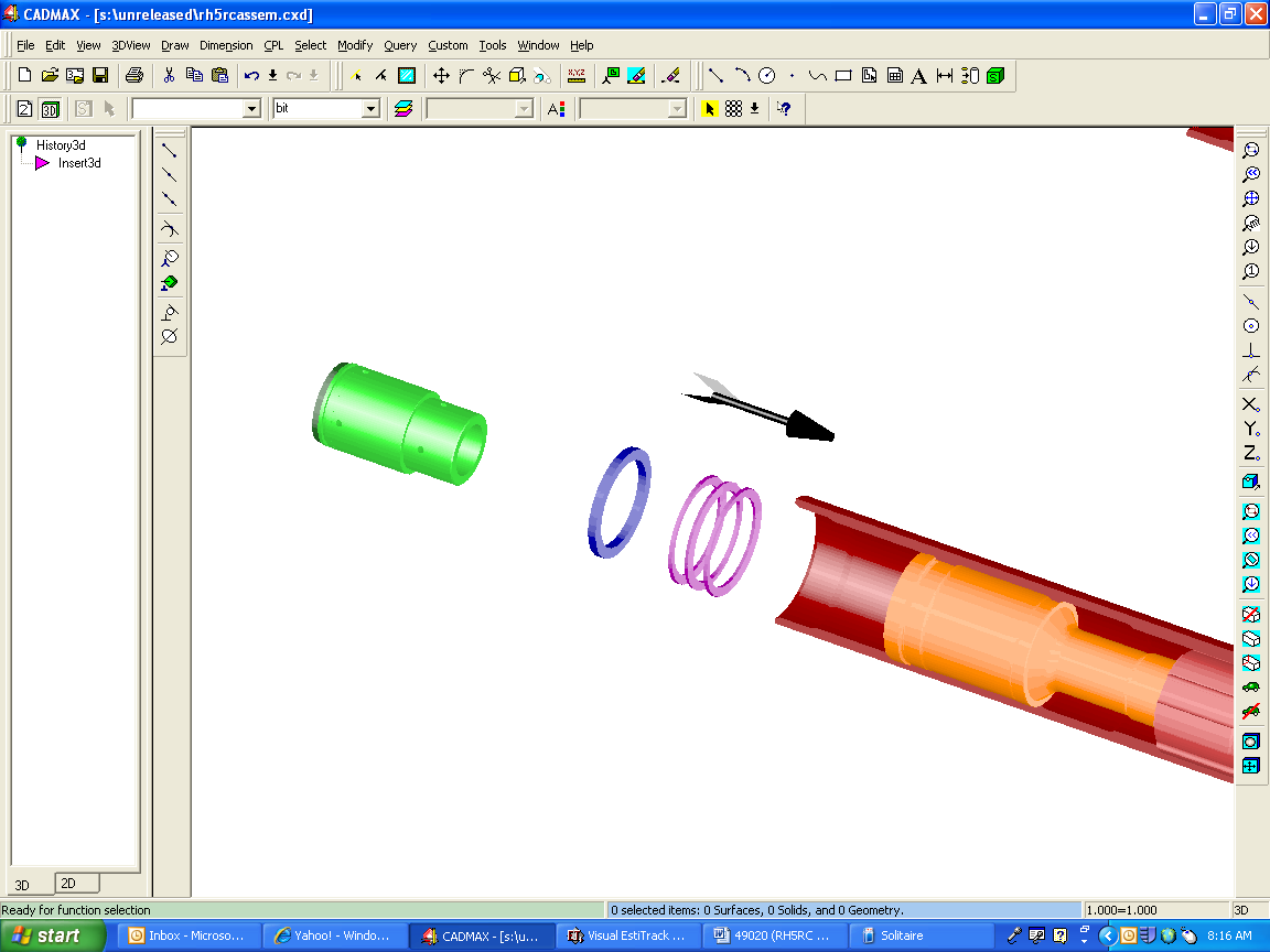
5. Lift out the check valve, check valve spring, washer and (3) disc springs.
6. Turn the bit/chuck assembly out of the wear sleeve.
7. With the bit standing, lift the shroud off. Pull the bit retainer ring from around the top of the chuck. And last lift the chuck up off the bit.
8. Remove the air distributor and piston. Using a steel or bar, push the piston against the air distributor. Continue pushing on piston to push out both parts. Moderate force and hammering may be needed to push the piston out depending on the condition of the inside of the hammer. Extreme loads may be needed if the parts are rusted or if the hammer is full of debris.
9. Removing the cylinder retainer ring. Pry one end out of the groove and lift. Once the ring is worked out of the groove it can be removed by hand.
9. Remove the cylinder. Stand the sleeve on the chuck end. Drop the piston back into the sleeve. It will drop to the cylinder. If needed, use the steel bar and continue pushing/driving on the piston until the cylinder hits the floor. Lay the sleeve over and push/drive the cylinder and piston out.
Disassembly is complete.
3.3 Inspection
Before cleaning any parts, observe them for oil. If the hammer is being properly lubricated, the parts should have a substantial film of oil all over but not dripping.
None of the following should be found inside:
dirt and grit
metal shavings
grease (other than at the chuck & backhead)
rust and corrosion
Clean all parts. Carefully look over all parts for cracks, corrosion, and pitting. Any corrosion indicates the hammer is not being oiled properly. Corrosion greatly increases the chance of cracks starting. Removed any and all corrosion using fine emery paper.
Galling- is surface damage caused by metal-to-metal contact under high loads. Many of the parts listed will be checked for galling. Any sign of galling indicates lack of lubrication, use of the wrong type of lubricant, or parts have been damaged to the extent there is interference between parts.
The clearance checks given below are what Rock Hog considers as the limit of wear for those parts. Past this point, the hammer performance will no longer be satisfactory. The clearance may be checked using feeler gages or measuring both parts with micrometers. These clearances may or may not be acceptable for your given application. With so many variables (air supply, rig settings, rock formation, etc) affecting hammer performance, only the operator can say when hammer performance has dropped below an acceptable level. Again, keeping a log of when & what service was performed will help fine-tune the service schedule to fit your operation.
Backhead: be sure to remove all the old grease from the drill pipe connection threads. Moisture can get trapped under the grease and corrode the surface. This also allows for a visual check of wear on the threads. Compare the worn threads to a new thread. If 50% of the thread form is worn away, replace the backhead.
Check the condition of the o-ring. If it is cracked, cut, or brittle, replace it.
Check the large threads for galling. Polish out any damaged areas.
Check that the snap ring holding the adapter tube is seated in properly. Make sure the adapter tube has no excessive movement inside the backhead.
Check the o-ring in the bottom of the adapter tube. If it is cracked, cut, or brittle, replace it. Even if the o-ring looks in good condition, always replace this o-ring for every (3) to (4) center exhaust tubes replaced.
The outside of the backhead will wear away. This wear is not detrimental to the function of the hammer but will eventually allow the drill pipe to wear away. Replace the backhead if it is no longer protecting the drill pipe.
Check Valve: check the condition of the rubber top and o-ring. If the seals are degraded, replace the check valve. If the clearance with the air distributor bore is greater than .015” (.4mm), replace the check valve.
Check Valve Spring: inspect the spring for wear and cracks. Make sure it still has memory and returns to its original length after being compressed.
Disc Springs and Washer: Replace any parts that are cracked or damaged. Look for wear on the faces of the washer and springs. As the faces wear, there is less compression force created by the springs. This compression is set by the compression gap described in section 3.4-step 8.
Air Distributor: make sure all the air holes are clear. Check the clearance of the stem end with the back bore in the piston. If it exceeds .015” (.4mm) replace the air distributor.
Check the condition of the o-ring inside the bottom end. If it is cracked, cut, or brittle, replace it. Even if the o-ring looks in good condition, always replace this o-ring for every (3) to (4) center exhaust tubes replaced.
Piston: check the (3) outside guide diameters, and top bore for galling and burning. Polish out any minor damage found on the surfaces.
Any black areas on the surface indicate the piston was rubbing and over heating. Surface heating is very detrimental to the piston. In most cases, if the surface is black, that surface will also be covered with cracks. Replace the piston if it has excessive surface cracks.
Check the clearance of the piston’s big diameter with the sleeve bore. If it exceeds .012” (.30mm), replace the wear sleeve. Check the old piston to the new sleeve bore. If the clearance exceeds .009” (.23mm), replace the piston.
Check the strike face for chipping and pitting. Replace a piston with a badly damaged strike face. Note: the face can be reconditioned by removing up to .04” (1mm) of material. Only a qualified machinist should do this. Reconditioned pistons are not covered under warranty.
Remove any nicks, dents, burrs with fine emery paper or a fine honing stone.
Again look over the piston for any rust, corrosion, pitting. All these will lead to cracks and failure of the piston.
Cylinder: check the inside bore for galling with the piston. Polish out any surface damage.
Check the clearance of the bore with the top diameter of the piston. If it exceeds .012” (.30mm), replace the cylinder. Check the new cylinder to the used piston. If the clearance exceeds .009” (.23mm), replace the piston also.
Wear Sleeve: Check the outside of the wear sleeve. If one end is wearing more than the other, flip the sleeve when the smaller end wears down to 4-7/16” (113mm). This will give additional sleeve life. Once any location on the sleeve wears down to a 4-1/4” (108mm) diameter, replace the sleeve.
Check the bore where the piston runs and the threads for galling. Polish out any surface damage.
Chuck: check the large threads for galling. Polish out any damaged areas.
Check the splines. The driving side will wear away. If the form of the driving side still matches the bit, the chuck is usable. If the form no longer matches the bit or more than ½ the spline thickness is worn away, replace the chuck.
Check the surfaces of the driving square that the shroud locks to. If badly worn, replace the chuck.
Shroud: look for cracks all over. Replace if any cracks are visible.
Any shroud can be used until the outside is worn down to 5.0” (127mm). As long as the driving square is in good condition, the shroud can be used provided it matches to the bit size being run.
Be aware that if the outside is rebuilt with weld, the square drive will become distorted. This may cause the shroud to not fit the chuck.
Center Tube: on the Metzke, check the outside of the collar where the inner-tube seals. Make sure the sealing diameter is not damaged. On the Remet, replace any cut or torn o-rings in the collar where the inner-tube seals.
Check the wear on the tube’s center hole at the collar end. If the hole measures 1.5” (38.1mm) or larger, replace the tube.
Check the length of the tube from the shoulder under the collar to the end of the tube. If the length is 36.3” (921mm) or shorter, replace the tube.
If a used tube will be reinstalled, make sure there are no sharp corners or burrs on the bottom edge. This edge must be smooth so it does not cut the o-rings when installed.
3.4 Assembly
1. Make sure all parts are clean and rust free. Wash and wipe off and/or blow out any dirt. Apply a light coat of oil to all internal parts.
2. If a used sleeve is being used, mark which end will be the backhead end and chuck end. If the sleeve is new, start with either end since the sleeves are reversible.
3. Install the cylinder in the chuck end of the sleeve. The cylinder end with the square cut-outs goes in first. Push it in as far as possible, then use a steel bar to tap in until it seats. When in position the cylinder will be 5-1/16” (128mm) from the end of the sleeve.
4. Install the cylinder retainer ring. Push the ring down into the sleeve then roll it over and push it into the groove.
5. Install the piston. With sleeve laying horizontal, slide the piston, small end first, into the backhead end of the sleeve. Push the piston in until it is against the cylinder. Note that the piston may stick some as it passes grooves in the sleeve. If the piston will not slide all the way in, remove the piston and correct the problem. Look for dirt, rust, and burrs. Once the piston is in, stand the sleeve on the chuck end and squirt some oil around the inside of the sleeve so it will run down around the piston.
6. Install the air distributor. Stand the sleeve on the chuck end. Install the o-ring in the bottom of the air distributor and put a coating of grease on the o-ring. Drop the air distributor, small end first, into the sleeve then use a steel bar to tap in until it seats. When in position the cylinder will be about 5” (127mm) from the end of the sleeve.
7. Set in the disc springs. Make sure the bevel on the springs alternate.

Set in the washer and check valve spring. Oil the outside of the check valve and set into the air distributor. Push the check valve down and make sure the spring pushes it back up. The check valve must move freely.
8A. Check the backhead compression gap. This gap is critical for keeping the internal parts tight.
With the o-ring off of the backhead, thread the backhead into the sleeve until it is hand-tight.
Measure the gap between the backhead shoulder & sleeve face. If it is greater than .17” (4.3mm), a part is out of position. If it is less than .04” (1.0 mm), perform one of the following:
Install a make-up washer. Either:
Purchase and install Rock Hog part #943021
between the disc springs and air distributor
or
Obtain and install a steel washer (3.98 OD x 3.12
ID x .060 THK) between the disc springs and air distributor
Check the gap again. If the gap is still less than .04 and a make-up washer is already in the hammer, replace the disc springs and check the condition of the air distributor shoulder and mating wear sleeve shoulder. Replace any worn parts. Assemble the hammer without the make-up washer, and check the gap. If the gap is still less than .04, put (1) new make-up washer back in.
8B. Once the gap is correct, remove the backhead, put the o-ring in the groove in the backhead. If the adapter tube needs installed, put it into the backhead and install the retainer ring. Install the o-ring in the bottom of the adapter tube and put a coating of grease on the o-ring. Apply thick coating of copper coat grease to the backhead wear sleeve threads. Turn the backhead into the sleeve until hand tight.
9. Install the center exhaust tube. Put a coating of oil over the entire outside of the tube. Slowly push and turn the tube into the hammer. There will be resistance as the tube’s guide diameters pass the o-ring in the adapter tube and air distributor. Push the tube in until it seats on the adapter tube.
10. Install the bit. Apply a coating of no-gall grease to the bit splines. Set the chuck down over the bit shank. Put the two halves of the ring back into the chuck. Set the shroud (the shroud diameter must be matched to the bit, normally the shroud is about .06” (1.5mm) smaller than the bit) down over the bit/chuck. Turn the shroud until its square drive drops onto and locks with the chuck’s square drive. Coat the threads with no-gall grease.
Thread the chuck back into the wear sleeve. The shroud will seat right onto the sleeve. There should be no gap.
If a bit is not going into the hammer, it is recommended that a shroud still be put on the chuck. This will protect the chuck from being damaged.
Assembly is complete.
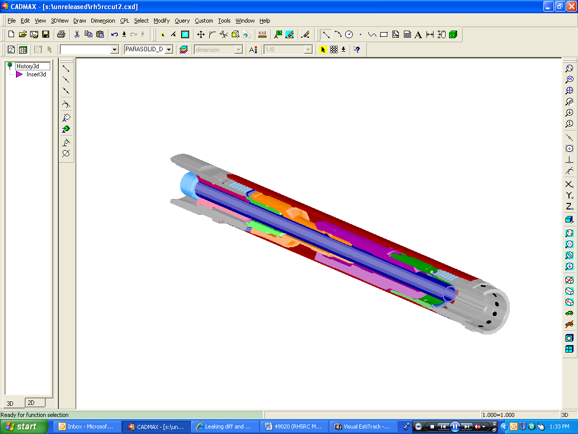
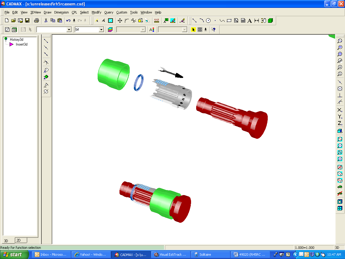
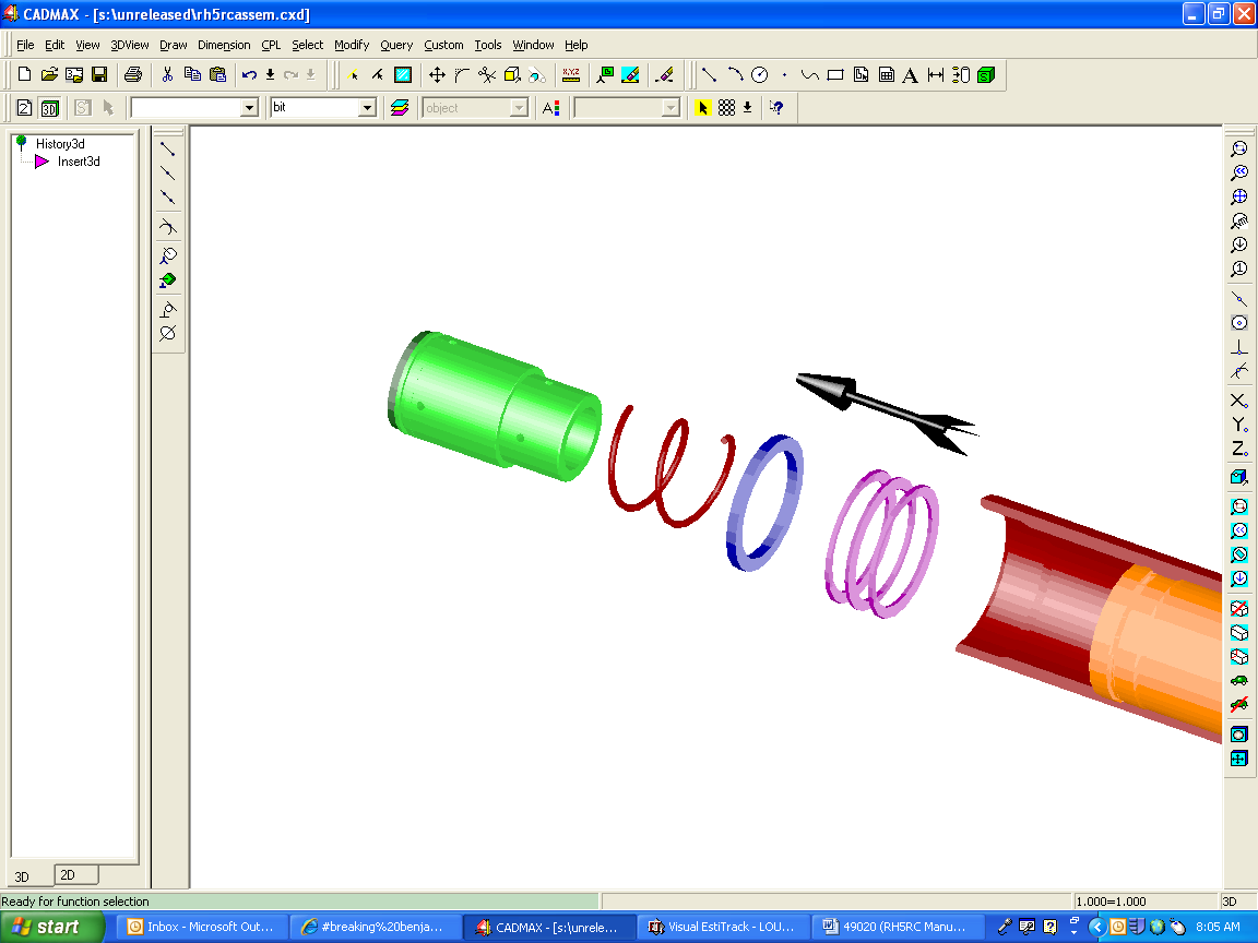
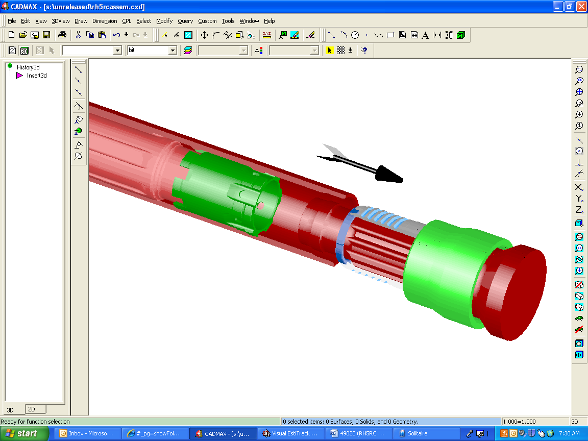
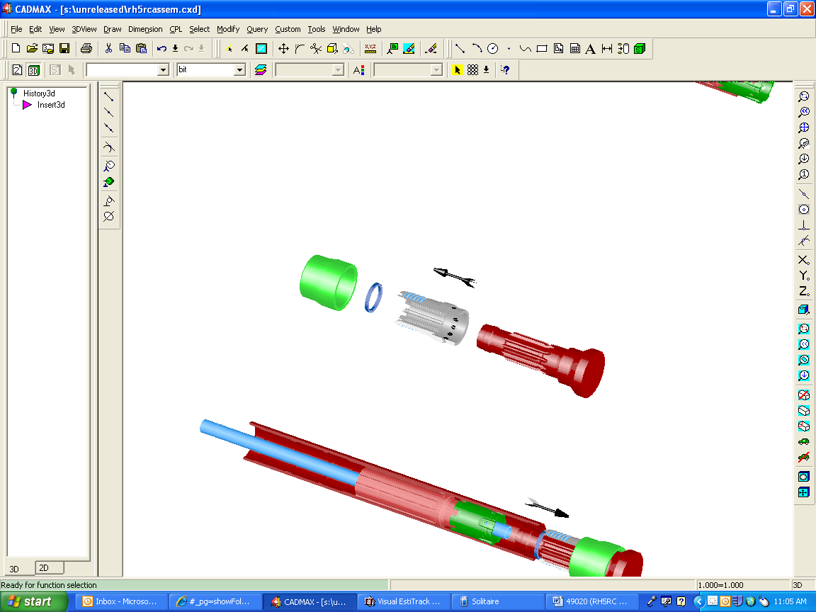
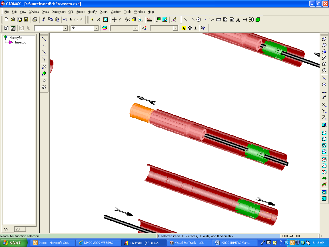
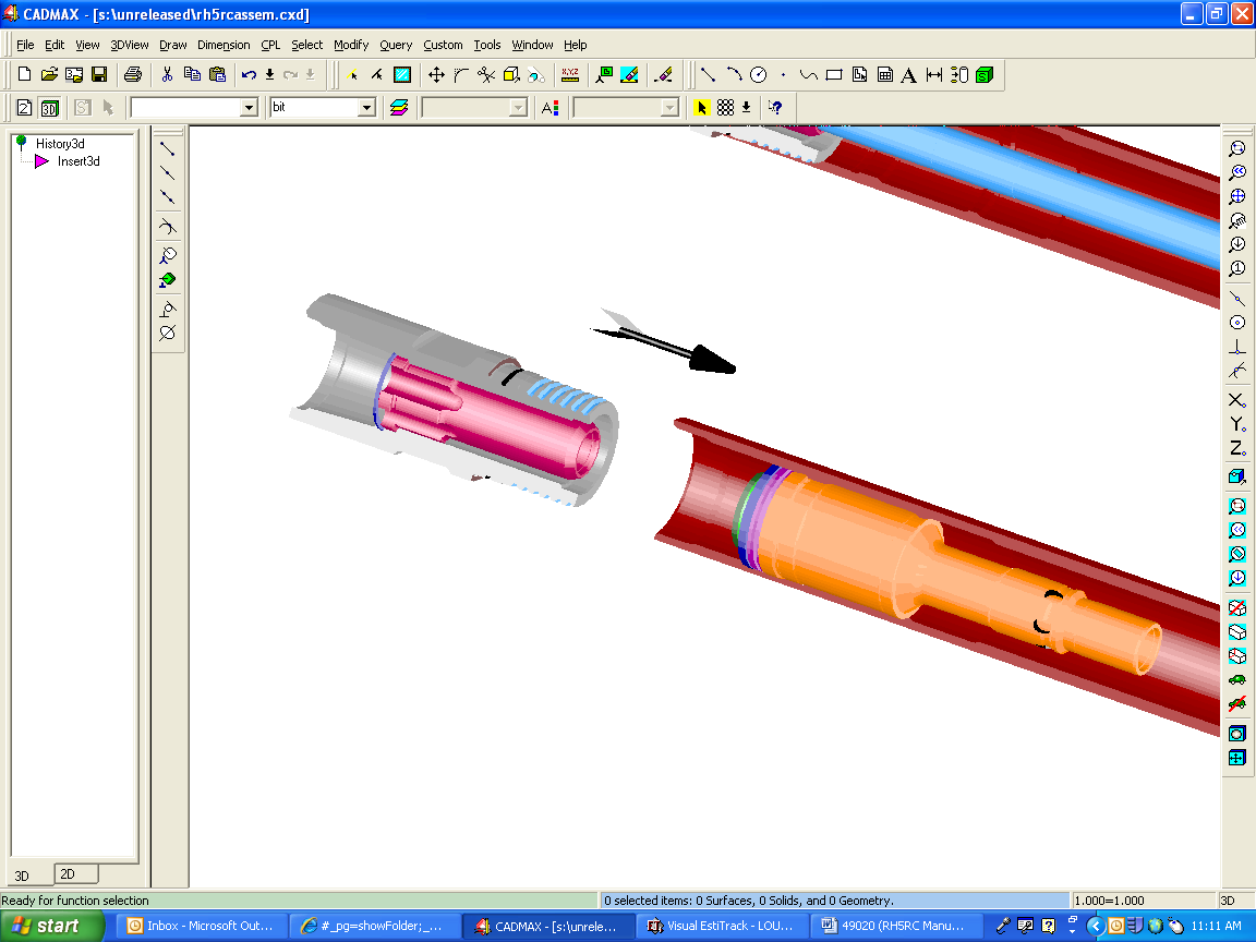
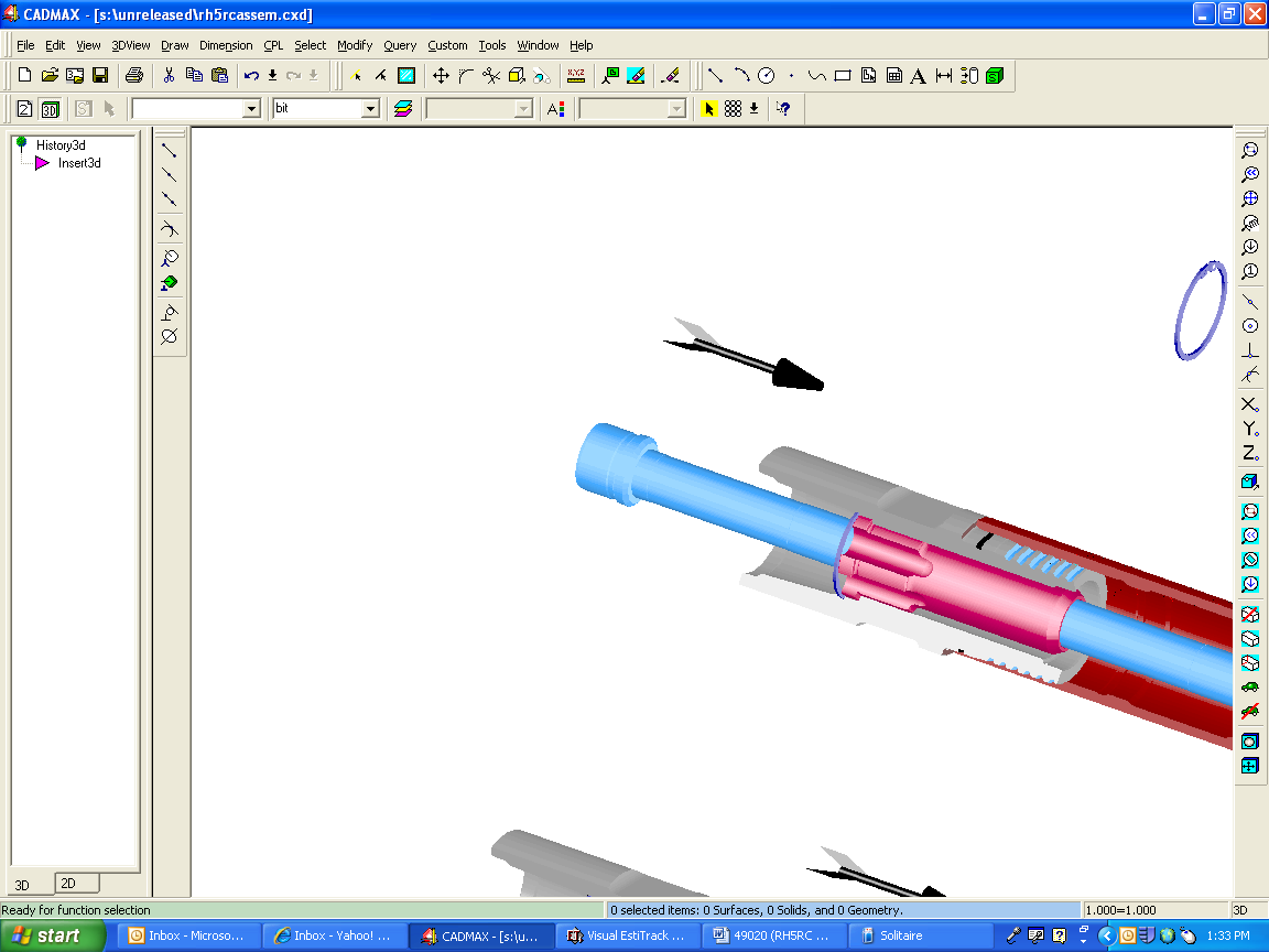
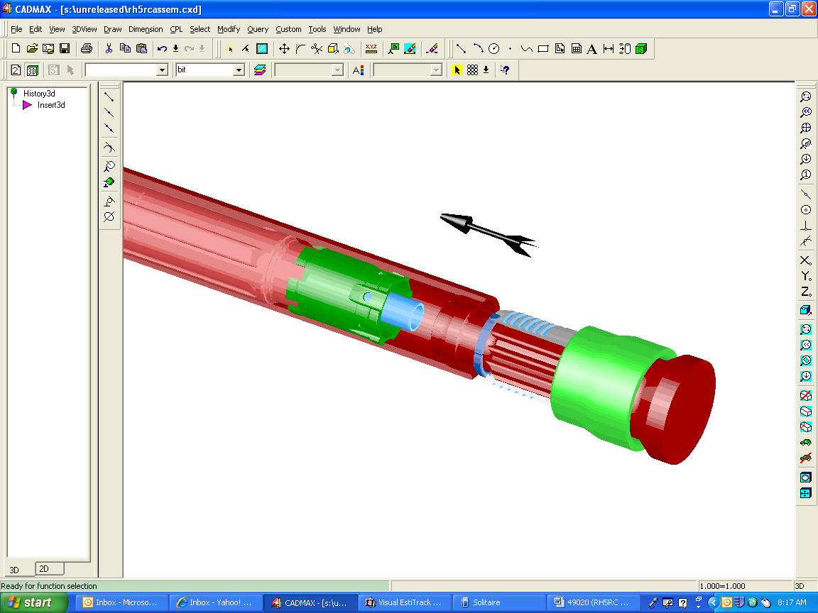
Section 4. Parts Breakdown
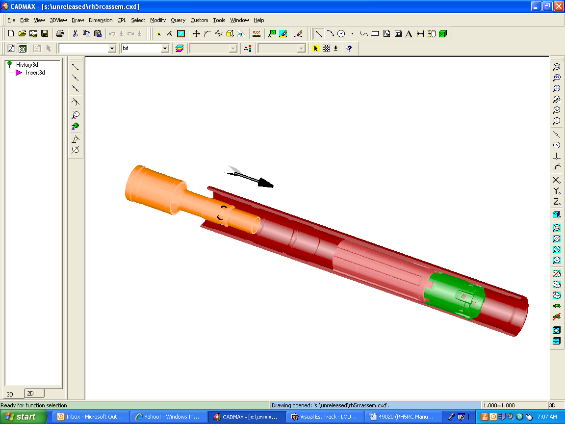
Exploded View
Assembled View
Part List
Shown at the right side of the chart is the quantity of spare parts that should be kept on hand. Level 1 is for local drilling, Level 3 is for very remote drilling.

Section 5. Trouble Shooting
These are typical problems that can develop after the hammer has been in service:
Possible Causes
Piston will not cycle
1. Center tube is worn back to far
2. Piston stuck in sleeve due to
Sleeve was pinched shut with wrench when threads were being loosened/tightened
Foreign material entered through drill string and jammed piston
Mud backed up into hammer (drilling under water), inspect the check valve
3. An internal part failed
Slow penetration, pressure ok
1. Dull or broken buttons on bit
2. Shroud is binding in hole
2. Incorrect drill rotation or down pressure for the formation being drilled
3. Harder rock formation than the normal
Low pressure
Leak in the air line
Leak in the hammer (cracked or broken part)
Hole worn thru center tube
Compressor output problem
High pressure
Air line is partially closed off
Foreign material clogging air passages in hammer
Bit blow holes are clogged
Poor cuttings sample
Shroud is worn too far under the bit
A hole is worn thru the sample tube

Rock HogRock Drilling Products
Manual No. HW-49020 Issued 2-10-09
(717) 328-9808 FAX (717) 328-5010 EMAIL [email protected]
Tags: drilling products, hogrock drilling, drilling, hogrock, products, operation, rh5rc, recirculation, hammer
- SCIENTIFIC WORKING GROUP ON GRANULOCYTE AND CONSTITUTIONAL MARROW FAILURE
- RESUMEN EN ESTE TRABAJO SE PROPONE UN MODELO JERÁRQUICO
- RESUMEN DE ACUERDOS ADOPTADOS EN LA REUNIÓN ORDINARIA DEL
- THE INFLUENCE OF A BYPASS ROAD ON URBAN DEVELOPMENT
- PERATURAN JAKSA AGUNG REPUBLIK INDONESIA NOMOR PER066AJA072007
- 24 PRAKATA MANUSIA MODERN YANG SIBUK MEMIKIRKAN
- CHINA (UPDATE 25 NOV 05) REMARK FOR HONG KONG
- TERBATAS 9 BAB IV SURVEI HIDROOSEANOGRAFI UMUM SURVEI
- RESUMEN DE LA DISCUSIÓN DEL FORO FSN SOBRE BIODIVERSIDAD
- FUNDACIÓN EDUCACIONAL SANTA BERNARDITA LENGUAJE Y COMUNICACIÓN CUARTOS AÑOS
- 8 NODAĻA MAGNĒTISKAIS LAUKS AP VADU PA KURU PLŪST
- VÁLLALKOZÁSVÁLLALKOZÓ A13 ÜZLETI TERV AGRÁRHITEL (AZ ÜZLETI TERVET
- ARCHITECTURAL ASSOCIATION (INCORPORATED) CONFLICTS OF INTEREST POLICY ARCHITECTURAL ASSOCIATION
- NATASHA DEEN IAN ELLIOTT DISCREPANT EVENT BALLOONS & STATIC
- 4 ZÁVĚR ŠETŘENÍ VŠPO 07 PRVNÍ SVÉHO DRUHU PŘINESLO
- 8 GIANFRANCO TEODORO ATTORE AUTORE DOCENTE TEATRALE CELL
- SER POSITIVO ES UNA FORMA DE VIVIR MEJOR PERMITE
- JANUARY 13 2003 STATE WATER RESOURCES CONTROL BOARD WORKSHOP
- LEY FEDERAL DE CONSULTA POPULAR CÁMARA DE DIPUTADOS DEL
- TIPOGRAFÍA DIGITAL EN UNOSTIPOSDUROSCOM HEMOS RECIBIDO MULTITUD DE CORREOS
- 8 TC MALİYE BAKANLIĞI MILLÎ EMLÂK GENEL MÜDÜRLÜĞÜ SAYI
- PLAN PRILAGOĐAVANJAPRILAGODBE UPRAVLJANJA OTPADOM ZA RD UBORAK BUĐEVCI U
- DEPORTE ESCOLAR CURSO 2010 2011 RESUMEN DE CAMPEONES
- PLIEGO DE CONDICIONES QUE HA DE REGIR EL PROCEDIMIENTO
- TEKNIK SAMPLING TERMINOLOGI ELEMEN ADALAH UNIT DIMANA DATA
- MODELO DE SOLICITUD AL AMPARO DE LO QUE PREVIENE
- PAGE 2 PHYSICAL CAPACITIES ASSESSMENT FORM RE FILE
- 8 COMISION DE ETICA Y TRANSPARENCIA I LEY ORGÁNICA
- PROYECTO EDUCATIVO INSTITUCIONAL AMBIENTAL INSTITUCIÓN EDUCATIVA NUEVO HORIZONTE ESCUELA
- PASSOAPASSO PARA FAZER O CADASTRO NO PORTAL EDUCACIONAL
RESIDENT FOOD PREFERENCES THERAPEUTIC DIETS RESIDENT NAME DATE OF
 ÍNDICE HISTORIA 3 1 ANTIGÜEDAD 3 2 EDAD
CLAUDIO RODRÍGUEZ PORQUE NO POSEEMOS (LA MIRADA) PORQUE NO
 ANSÖKAN OM INSATSER ENLIGT LSS LAGEN OM STÖD OCH
[KOLSKA 20162017 GODINA P R I J A V
16 NCAC 06C 0384 MENTOR PROGRAM REQUIREMENTS (A) ALL
EDITO VRIJWILLIGERS IN DE MIST… TE VEEL IS TROP
 AN INDEPENDENT WATCHDOG AND SUPPORTER OF THE GLOBAL FUND
 EXERCÍCIOS PARA A UNIDADE III – (MORAES REVISADO POR
“ARIAL” “ARIAL BLACK” “ARIAL NARROW” “BOOKMAN OLD STYLE” “CENTURY”
MODELO DE COMUNICACIÓN AL PROTECTORADO DE LA CONSTITUCIÓN DE
O MEDICAL SERVICES UTSIDE PRACTICE AND OTHER BUSINESS ACTIVITIES
 JAMIESON SEE SECTIONS 1819 NEUTRAL CITATION NUMBER [2011]
NZQA UNIT STANDARD 17385 VERSION 7 PAGE 3 OF
REPRODUCIR EL SIGUIENTE ESQUEMA NUMERADO USANDO TAMBIÉN LAS TABULACIONES
OGŁASZAMY NABÓR REFERATÓW NA KONFERENCJĘ „INTERPRETACJA DLA OCHRONY DZIEDZICTWA
CONCLUSION TIME CONSTRAINTS DICTATED THAT THERE SHOULD BE A
INFORMÁTICA UNIVERSIDAD CARRERAS LA PLATA LIC EN INFORMÁTICA LA
 L’EXTRAORDINARI ENGINY PARLANT DEL PROFESSOR PALERMO TÍTOL L’EXTRAORDINARI
 TELEMEDYCYNA POLSKA SA UL MODELARSKA 12 40142 KATOWICE TEL
