AP3DBL AP3DBL 3INPUT AUDIO AMPLIFIER TABLE OF CONTENTS 1
AP3DBL AP3DBL 3INPUT AUDIO AMPLIFIER TABLE OF CONTENTS 1
Jocelyn
![]() AP3DBL
AP3DBL

AP3DBL
3-Input Audio
Amplifier
Table of Contents
4.1 Operations of Front Panel 5
4.3 Operations of Control Software 7
4.3.1 Connection with Computer 7
4.3.2 Installation/uninstallation of RS232 Control Software 8
4.3.5 RS232 Communication Commands 10
1.Introduction
1.1AP3DBL Product Info
The KanexPro AP3DBL is a 3-Input 40-Watt audio amplifier supporting 70V or 100V. It comprises of 3-switchable inputs (RCA, 3.5mm and TOSLINK) for quick switching and sound reproduction. The audio amplifier supports MIC mixing and EQ control perfect for classrooms, conference rooms, lecture halls and restaurants.
Note: The unit includes IR remote & sensor. Please make sure the contents are supplied in the box or contact your reseller immediately.
1.2Features
Ultra-fast switching audio amp
Mono audio output at 40Watt.
Switchable between 70V and 100V.
Supports ducking function
16-ID codes for controlling between different AP3DBL amplifiers.
3-level MIC input, supports condenser microphone, dynamic microphone and wireless microphone.
MIC port can support balance/unbalance signals & suppresses the external noise effectively.
Two stereo audio inputs and one digital audio input, switchable by button, IR remote & RS232.
Volume/Bass/Treble controllable by buttons, IR remote & RS232.
Convection cooled
LED indicator, for power and working status.
Antistatic case design.
1.3Package Contents
1 x AP3DBL
1 x Power adapter (DC 24V)
2 x Mounting ears
1 x RS232 cable
1 x IR remote
1 x IR receiver
4 x Screws
1 x User manual
2.Product Appearance
2.1Front Panel
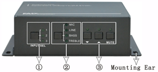
Figure 1 Front Panel
|
No. |
Name |
Function |
|
1 |
Audio Input Selection |
To select the input audio source, after choosing the audio source, the corresponding LED indicator will be on. No.1 is for dual mono audio input (2 RCA connectors for L&R), No.2 is for stereo audio input (3.5mm mini jack), and No.3 is for digital fiber audio input. |
|
2 |
Audio Control |
Adjust the volume of the MIC, Line, or the level of Bass and Treble with this button |
|
3 |
Volume Adjustment |
To turn up/down or mute the corresponding audio. ▽: Turn down the volume △: Turn up the volume MUTE: Mute the output |
2.2Rear Panel
Figure 2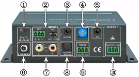 e
2 Rear Panel
e
2 Rear Panel
|
No. |
Name |
Function |
|
1 |
Power Indicator |
Turns red when power on. |
|
2 |
Microphone input port |
3-pole captive screw connector for microphone input, the dial switch in right side is to select the micro input kind, including 48V (for condenser microphone), MIC (for dynamic microphone) and LINE (for line audio). |
|
3 |
Audio Inputs |
3.5mm mini jack for stereo audio input, it can be connected with audio source device such as DVD player. |
|
4 |
ID Code |
16 codes range from 0 to F (hexadecimal), works together with the PC control software. |
|
5 |
IR Eye |
To connect with the IR receiver, works together with the IR remote. |
|
6 |
Power Port |
To connect with the power adapter (DC24V). |
|
7 |
2 x RCA |
Dual-mono audio input, which can be connected with audio source device such as a PC. |
|
8 |
Digital Audio Input |
Fiber connector for digital audio input, it can be connected with a device with fiber port, such as blue-ray player. |
|
9 |
RS232 |
3-pole captive screw connector for serial control, it can be connected with PC (Use a 3-pole captive to 9 pin female D connector and serial control software) to control AP3DBL. |
|
10 |
Audio Output |
To connect with audio output devices, such as speakers (To select 70V or 100V depends on the input voltage of the speakers). COM is for grounding (GND). |
3.System Connection
3.1Usage Precautions
Make sure to connect everything before powering on.
Speakers must be connected before powering on.
3.2System Diagram
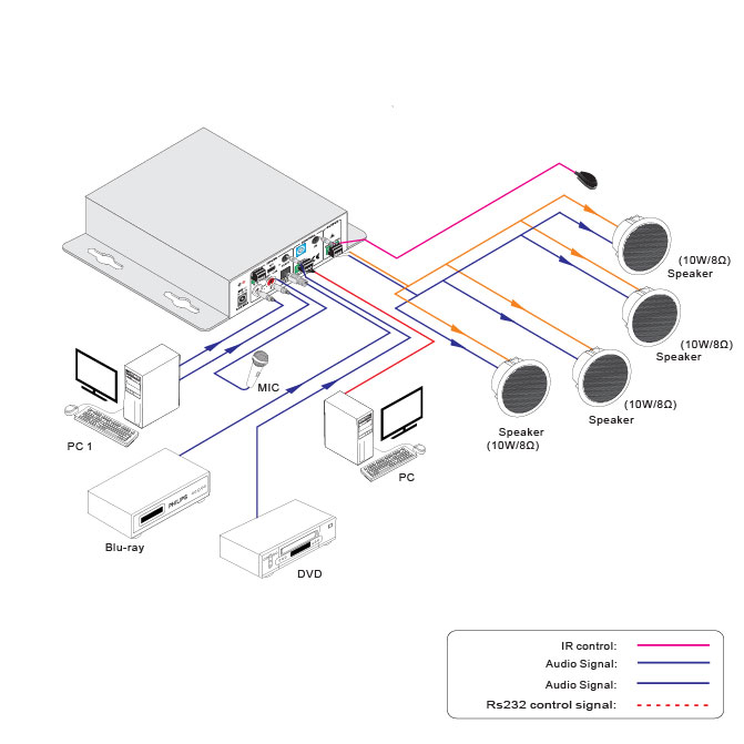
Figure 3 System Diagram
3.3Audio Signal Connection
3.3.1Audio Output
AP3DBL supports mono audio output, and the output voltage is 70V or alterative 100V. With its dual-purpose design, it can be applied in different areas. The end COM is for grounding. The amplifier to be connected is mono audio output with a rated power at 40Watt, so AP3DBL can be connected with several speakers in parallel connection way (Total power mustn’t be more than 40Watt).
The following figure shows us how to connect with the speakers. Here we take the speakers 10Watt@8Ohms for each as example.
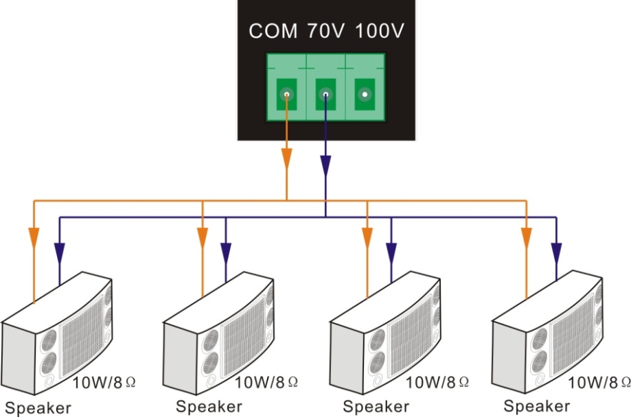
Figure 4 Audio Output Connection
3.3.2Audio Inputs
AP3DBL provides with 2 stereo audio inputs, one microphone input and one digital fiber audio input. The following figure shows the audio input ports.
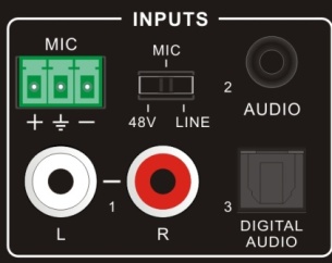

Figure 5 Audio Input Ports
48V phantom power input
When
the switch turns to “48V” (It has a good frequency
characteristic, high input impedance and high sensitivity in this
mode), the MIC input will provide a 48V phantom power. This is
usually used for power supply for condenser microphone, Connection
is: “+” connects to positive, “-” connects to
negative and “![]() ”
to ground.
”
to ground.
Note: In this mode, only condenser microphone can be connected with.
MIC input
When the switch turns to “MIC” (It has a low frequency characteristics, and wide frequency response in this mode), the microphone input is used for connecting with dynamic microphone. There are two different connections:
Unbalanced connection:
“+”
and “![]() ”
connect to ground, and “-” connects to signal.
”
connect to ground, and “-” connects to signal.
“-”
and “![]() ”
connect to ground, and “+” connects to signal.
”
connect to ground, and “+” connects to signal.
Balanced connection: “+” connects to positive, “-”
connects to negative and “![]() ”
connects to ground.
”
connects to ground.
LINE input
When the switch turns to “LINE” (It has a low frequency characteristics, and wide frequency response in this mode), the microphone input is used for connecting with normal audio or wireless microphone output. There are two different connections:
Unbalanced connection:
“+” and “![]() ”
connect to ground, and “-” connects to signal.
”
connect to ground, and “-” connects to signal.
“-” and “![]() ”
connect to ground, and “+” connects to signal.
”
connect to ground, and “+” connects to signal.
Balanced connection: “+” connects to positive, “-”
connects to negative and “![]() ”
connects to ground.
”
connects to ground.
Digital Audio Input
AP3DBL provides with a fiber optical port to connect with digital audio source device. With the SPF optical fiber, the audio signal can be transmitted faster, more stable, reliable, and can be transmitted over a long distance without distortion.
3.4System Applications
AP3DBL can be applied in different occasions, such as classroom, small meeting room, lecture hall, bar and hotel etc.
4.System Operations
4.1Operations of Front Panel
The buttons provides the control of volume/EQ control and switching. The LED indicator will show the connecting status. The following content introduces audio switching and EQ control in detail.
Operations: Press the corresponding button again for cyclic switching.
4.1.1Audio switching
There are three switchable audio inputs, one 2xRCA input, one 3.5mm jack input, and one digital fiber audio input, switchable through the buttons as below:
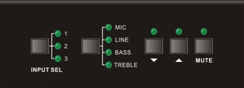

Figure 6 Audio Source Selection Button
4.1.2Volume/EQ controlling
The buttons can control the line volume and MIC volume.
The buttons, and controlled up/down/mute will select the MIC Volume/LINE volume/LINE bass/LINE treble by the function buttons. Please check the picture below:
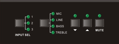


Figure 7 Audio Mode and Volume Adjustment buttons
For example, to turn up the line volume, you should select the “LINE”
first, and then press the button “ ”.
”.
4.2Operations of IR Remote
AP3DBL provides with an IR eye, with the IR Receiver and the IR remote, user can control AP3DBL remotely.
Notice: The IR Receiver and the IR remote are all offered for charge.
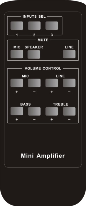
Figure 8 IR Remote
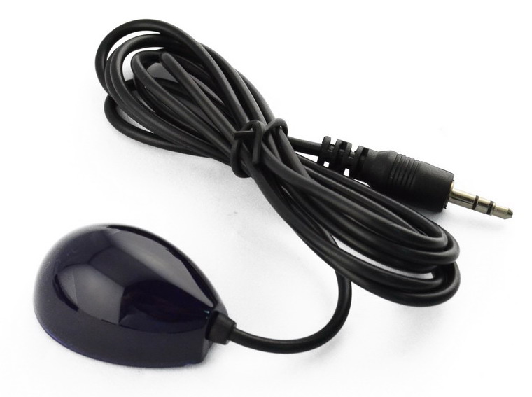

Figure 9 IR Receivers
4.3Operations of Control Software
4.3.1Connection with Computer
When the amplifier connects to the COM1 or COM2 of the computer with control software, users can control it by that computer.
To control the amplifier, users should use a 3-pole male captive screw to 9-pin HD female connector and use the public COM software.

Figure 10 Connection of RS232 Port
4.3.2Installation/uninstallation of RS232 Control Software
Installation
Connect the input source devices and the output device according to the system diagram.
Copy the RS232 control software to one computer, and then connect the RS232 port of this computer and AP3DBL.
Double-click the EXE program to execute the software.
Here we take the software CommWatch.exe as example. The icon is showed as below:

Figure 11 Control Software
Uninstallation Delete all the control software files in corresponding file path.
4.3.3Running Environment
While the control software is installed, we can activate the software through the RS232 port and set the parameters, to make it able to send RS232 commands to control AP3DBL.
4.3.4Function Settings
With the control software, we can easily switch the input channel, mute the output, check the working status, and adjust the volume etc. Please refer the details in RS232 Communication Commands.
T he
interface of the control software is showed as below:
he
interface of the control software is showed as below:
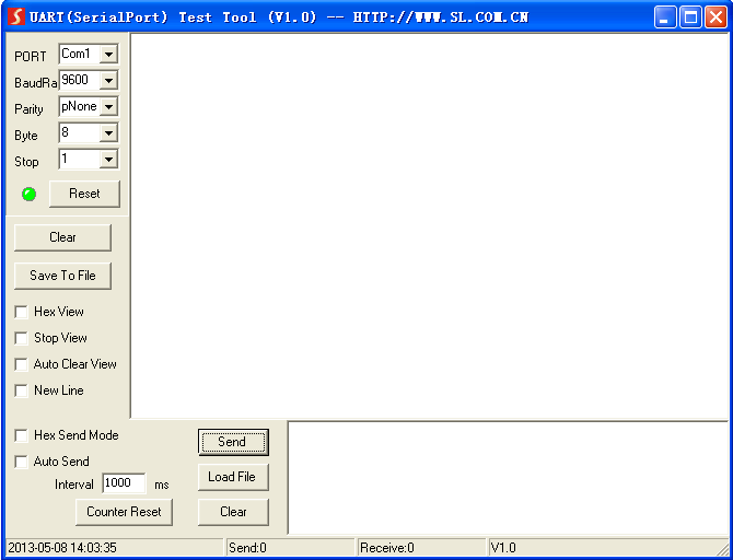
Figure 12 Main Interface of Control Software
4.3.5RS232 Communication Commands
Communication Protocol: RS232 Communication Protocol
Baud rate: 9600 Data bit: 8 Stop bit: 1 Parity bit: none
Notice:
The letter inside bracket [ ] is the variable code, which is changeable.
The bracket [ ] is not included to the RS232 commands.
Any dot “.” after the letters is part of the commands.
Ducking function:
When input with MIC, the volume of the line audio will be automatically turned down to the preset volume level, if there is no input MIC audio signal after 5 seconds, then the volume will be automatically turned up to the original one. If you need to disable/enable the ducking function, just send the command “610%” again.
ID coding
The ID codes of AP3DBL ranges from 0 to F (hexadecimal), when sending RS232 commands, please take notice of the address of the ID code.
If the address of the ID code is 0, any RS232 command is available.
If the address is in 1~F, it has one unique ID code (If the ID code is not the same with the address, no RS232 command will work).
While the ID code is in 1~F, please add “ID/” before sending the command.
For example, if the ID code is 5, the RS232 command needed is “604%”, the correct command is in this format: 5/604%.
There is no need to add “ID/” before the command when the ID code is 0.
Examples:
Switching the input 2 to the line out, the command is: 2A1.
Turning up the volume of line audio, the command is: 603%
Preset the MIC volume to “21” degree, the command is: 521%
Checking the working status of AP3DBL, the command is: 600%
If the ID code is 0, sending command 601% is able to turn up the MIC volume.
If the ID code is 2, sending command 601% will not work, and the MIC volume remains unchanged. The right command is 2/601%.
5.Specifications
|
Audio Input |
Audio Output |
|||
|
Input |
2 stereo audio 1 MIC
|
Output |
1 amplifier 1 Stereo audio |
|
|
Input Connector |
2 RCA 1 3.5mm jack 1 3-pole 3.81mm captive screw connector
|
Output Connector |
1 Captive Screw 1 x 3.5mm Jack |
|
|
Input Impedance |
>10KΩ |
Output Type |
50Ω/stereo, 4~8Ω/Amplifier |
|
|
Audio General |
||||
|
Frequency Response |
120Hz ~ 20KHz |
CMRR |
>70dB@20Hz~20KHz |
|
|
SNR |
80dB (Max) |
Bandwidth |
120Hz ~ 20KHz |
|
|
Rated Power Output |
40Watt @8Ohms |
THD + Noise |
1%@1KHz, 0.3%@20KHz at nominal level |
|
|
Voltage Gain |
32dB |
|||
|
Control Function |
||||
|
RS232 Control |
1 3-pole 3.81mm captive screw connector |
Front Panel Control |
Buttons |
|
|
ID Code Control |
16 ID codes for control. |
|||
|
Optional |
IR remote & TCP/IP controlled |
|||
|
General |
||||
|
Temperature |
-20 ~ +70℃ |
Humidity |
10% ~ 90% |
|
|
Power Supply |
DC 24V power adapter |
Power Consumption |
5W |
|
|
Case Dimension |
1.5"x3.78"x3.45" (HWD) |
Product Weight |
0.67 lbs. (0.3Kg) |
|
6.Panel Drawing
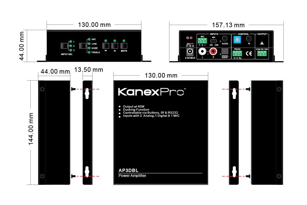
Figure 13 Panel Drawing
7.Troubleshooting and Maintenance
When there is no output audio:
Check if there is any signal at the input.
Check if there is any signal at the output.
We can check these by using an oscilloscope or a multimeter. If there is no signal input/output, maybe the input/output cables broken or the connectors loosen, please change for another cable.
Check if the output port number is the same with the controlled one.
If not the problem mentioned above, probably there is something broken inside the unit; please contact technical support
If the POWER indicator doesn’t work or no respond to any operation, please make sure the power cord connection is good.
If the output sound is interfered, please make sure the system is grounded well.
If the static becomes stronger when connecting the audio connectors, it probably due to bad grounding, please check the grounding and make sure it connected well, otherwise it would damage the amplifier.
If the keys on the front panel, RS232 port or the IR remote, cannot control the AP3DBL amplifier the unit could be defective please contact technical support.
8.Safety Operation Guide
In order to guarantee the reliable operation of the equipment and safety of the staff, please abide by the following proceeding in installation, using and maintenance:
The system must be earthed properly. Please do not use two blades plugs and ensure the alternating power supply ranged from 100v to 240v and from 50Hz to 60Hz.
Do not put the switcher in a place of too hot or too cold.
As the power generating heat when running, the working environment should be maintained fine ventilation, in case of damage caused by overheat.
Please cut off the general power switch in humid weather or left unused for long time.
Before following operation, ensure that the alternating current wire is pull out of the power supply:
Take off or reship any components of the equipment.
Take off or rejoin any pin or other link of the equipment.
As to non-professional or without permission, please DO NOT try to open the casing of the equipment, DO NOT repair it on your own, in case of accident or increasing the damage of the equipment.
DO NOT splash any chemical substance or liquid on the equipment or around.
9.Warranty
A. LIMITED WARRANTY
KanexPro TM warrants that (a) its products (the “Product”) will perform greatly in agreement with the accompanying written materials for a period of 3 years from the date of receipt and (b) that the product will be free from defects in materials and workmanship under normal use and service for a period of 3 years.
B. CUSTOMER REMEDIES
KanexPro’s entire liability and Customer’s exclusive remedy shall be, at KanexPro option, either return of the price paid for the product, or repair or replacement of the Product that does not meet this Limited Warranty and which is returned to KanexPro with a copy of customers’ receipt. This Limited Warranty is void if failure of the Product has resulted from accident, abuse, or misapplication. Any replacement Product will be warranted for the remainder of the original warranty period of 3 year, whichever is longer.
C. NO OTHER WARRANTIES
To the maximum extent permitted by applicable law, KanexPro disclaims all other warranties, either express or implied, including, but not limited to implied warranties of merchantability and fitness for a particular purpose, with regard to the product and any related written materials. This limited warranty gives customers specific legal rights. Customers may have other rights depending on the jurisdiction.
D. NO LIABILITY FOR DAMAGES
To the maximum extent permitted by applicable law, in no event shall KanexPro be liable for any damages whatsoever (including without limitation, special, incidental, consequential, or indirect damages for personal injury, loss of business profits, business interruption, loss of business information, or any other pecuniary loss) arising out of the use of or inability to use this product, even if KanexPro has been advised of the possibility of such damages.
![]()
Brea, California
KanexPro.com
MPN: AP3DBL
HDMI are trademarks or registered trademarks of HDMI Licensing LLC in the United States and other countries. KanexPro is a trademark of Apogee Inc., registered in the U.S.
Tags: ap3dbl ap3dbl, mpn: ap3dbl, ap3dbl, contents, 3input, table, audio, amplifier
- EJERCICIOS TRIGONOMETRÍA NOMBRE FECHA 1 DE UN TRIÁNGULO
- JUDUL SKRIPSI FISIOTERAPI ANGKATAN 2013 MESOPHRYON NO NIM NAMA
- CONTACT DETAILS OF DIVISIONAL MANAGERS’ OFFICES DM – EAST
- EXPEDIENTE MODELO DE SOLICITUD DE LICENCIA DE AGRUPACIONSEGREGACION DE
- TRADUCCIÓN NO OFICIAL UNITED NATIONS NATIONS UNIES SECRETARIAT OF
- NZQA UNIT STANDARD 9005 VERSION 5 PAGE 3 OF
- 9 REGISTAR PROPISA OBJAVLJENIH U “SLUŽBENOM GLASNIKU OPĆINE
- SIGURNOSNOTEHNIČKI LIST PREMA UREDBI (EZA) BR 19072006 STRANICA 16
- THE GEOLOGY OF CALAVERA HILLS NORTH SAN DIEGO COUNTY
- REPUBLIC OF SEYCHELLES THIRD NATIONAL REPORT TO THE CONVENTION
- GENERIC MENTORING PROGRAM POLICY AND PROCEDURE MANUAL CUSTOMIZABLE TEMPLATE
- KROKSLÄTTSGYMNASIET MÖLNDAL KROKSLÄTTSGYMNASIETS MANUAL FÖR KÄLLHÄNVISNING OCH KÄLLFÖRTECKNING LÄSÅRET
- 419B875 PARTIES TO PROCEEDINGS RIGHTS OF LIMITED PARTICIPATION STATUS
- LA TEORÍA DEL ETIQUETAMIENTO O “LABELLING APPROACH” DE HOWARD
- ABOUT THE ESE V34 XML SCHEMA PURPOSE THE ESE
- TIPOS DE TEXTO LAS TIPOLOGÍAS TEXTUALES SON MÉTODOS
- CSO1232A (615) ARIZONA DEPARTMENT OF CHILD SAFETY OFFICE OF
- LANGAGES 146 2002 – VERSION PRÉLIMINAIRE HOMO NARRANS
- (NAZIV NADLEŽNOG UPRAVNOG TIJELA) ZAHTJEV ZA UPIS U REGISTAR
- STUDENT GOVERNMENT ASSOCIATION GRIEVANCE AND SUGGESTION FORM DATE
- BARCODES PASTEL ALLOWS YOU TO MAKE FULL USE
- AFFIX PHOTOGRAPH (CHOOSE FILE) HOSTEL ADMISSION FORM (NUST ISLAMABAD
- REQUISITOS MÍNIMOS PARA ARTEFACTOS DE TIRO FORZADO “DISPOSICIÓN INTERNA
- ANJ 5 ROČNÍK OPAKOVANIE 1 DO ZOŠITA VYSKLOŇUJ SLOVESÁ
- PROGRESIONES VERTICALES FONÉTICA BACKPACK GOING PLACES STAND
- PROGRAMA DE ACTIVIDADES CÍRCULO DE BELLAS ARTES DE MADRID
- FRAME1 LAPORAN BEBAN KERJA DAN EVALUASI DOSEN SEMESTER II
- HENVISNINGSSKJEMA TIL PP TJENESTEN HENVISNINGEN GJELDER ADRESSE TELEFON
- CURRECULUM VAITE OF DR HANAA YOUSEF ABDELHAKIM BAKIR ASSOCIATE
- 1020 E THOMAS STREET PASADENA TX 77506 TEL 7137400440
 2 1CPP FELLOWSHIP PROPOSAL – CANDIDATE RESPONSE TO HOST
 BANCO MUNDIAL Y COFIDES OFRECEN FINANCIACIÓN A LAS PYMES
 CÓDIGO Nº COMISIÓN DE DESARROLLO DEL PREGRADO CODEPRE SOLICITUD
 PENERAPAN 3D DALAM MENDIAGNOSA TMJ DENGAN PESAWAT CBCT3D DI
23 WRZEŚNIA W KSIĘGARNIACH I SKLEPACH INTERNETOWYCH RUSZA SPRZEDAŻ
THE CANTERBURY TALES PROLOGUE CHARACTER DESCRIPTIONS KNIGHT BIG
 LES SLOGANS DE LA GÉNÉRATION CLIMAT FICHE APPRENANTE ACTIVITÉ
 59 31 MAY 2012 REPORT ON G20 TRADE MEASURES1
 INFORME EJECUTIVO LA LIBERTAD INTENCIONES DE SIEMBRA CAMPAÑA AGRICOLA
 COLEGIO LUIS MUÑOZ RIVERA LISTA DE LIBROS Y MATERIALES
OBRAZAC PRIJAVE ZA JAVNI POZIV ZA DODJELU SPORTSKO
PRIEREZOVÉ TÉMY ROČNÍK PIATY PREDMET SLOVENSKÝ JAZYK A LITERATÚRA
 URBAN FOREST TREE PROTECTION TREE PROTECTION IN THE CITY
TRANSPORT THROUGH CONNECTIVE TISSUES DESCRIPTION WE WILL USE POROUS
INSTRUKCJA DO SPRAWOZDANIA Z REALIZACJI LSR (ZA CAŁY OKRES
1100 PÁGINA 3 DE 3 ASAMBLEAS CONCEPTO NO 09963
1 APPROVAZIONE VERBALI SEDUTA PRECEDENTE 1 INTERROGAZIONE URGENTE DEL
 20 RODZAJE NORM ZUŻYCIA RODZAJE ZAPASÓW I ICH STANY
ABIERTO EL PLAZO PARA SOLICITAR LAS SUBVENCIONES INDIVIDUALES TANTO
 UNIDAD NOMBRE DE LA UNIDAD NOMBRE DE LA
