OBJECT‑ORIENTED ANALYSIS REQUIREMENTS ANALYSIS AND DOMAIN ANALYSIS PRECEDE DESIGN
“STILL LIFE WITH FRUIT” OBJECT‑ORIENTED SOFTWARE ENGINEERING AN ARTISTOBJECT‑ORIENTED ANALYSIS REQUIREMENTS ANALYSIS AND DOMAIN ANALYSIS PRECEDE DESIGN
Themes of Object-Oriented Analysis and Design
Object‑Oriented Analysis
Requirements analysis and domain analysis precede design
So far we’ve looked at requirements analysis—understanding what the customer wants
Domain analysis understands the customer’s problem—by identifying the classes comprising a problem domain.
Design explores their contents, from outside in
What’s the difference between traditional or structured analysis and OO analysis?
Result of OO analysis is a representation of the classes of a problem domain (not functions)
Identifying classes is category‑formation
Objects simulate some slice of the world which a computer system models
Objects are a natural construct for simulation
Classes of objects are a natural way to organize classes
Infants learn to recognize objects and how to categorize them in their first few months
A key insight of the child psychologist Piaget; cognitive scientists have done further work
Adults rely on categorization to understand the world around them
We create new categories all the time, for example, new makes of cars
A problem with categories, however, is that they can be fuzzy and hard to define precisely
Natural kinds: how do you define an elephant? a game?
Prototypes: people see how close objects match a prototypical member of a category
Why is the fuzziness of natural kinds a problem for OOSE?
It's hard to be precise about defining categories
That's why we need a methodology for OOSE
Some categories are directly observable in requirements
Others are more abstract, implicit or arising from implementation needs
Candidate classes include:
Tangible things referred to by common nouns in requirements specification
or application domain (i.e., cookie, factory, triangle)
Events with associated information (i.e., flight, game).
Abstract data stores (i.e., buffer, tree, hash table)
External interface ports (i.e., terminal, printer, window, menu)
Complex processes or operations (i.e., sort, edit command)
Note: verbs can also be classes! Especially processes than store state information.
One might think of a scanner as an operation on tokens of class STRING
But a scanner's behavior probably deserves its own abstraction
As a subclass of STRING?
Can anything be a class? What isn't a class?
Indeed, category‑formation is a fundamental human activity
But there are practical limits: classes should have content, storing state information
Simple operations (e.g., QUIT)
Proper nouns (these are instances of classes, not classes)
Classes with just one or two routines (probably not worth classifying)
Redundant classes (merge synonyms, reuse classes in libraries)
Again: develop a glossary of terms—Why would this be especially helpful to OO analysis?
Brief dictionary‑like definitions denoting how the term is used in domain
Defining terms explicates the domain knowledge that you are modeling
Terms can help with the discovery of classes and their structure
Maintain glossary files throughout development, finally as documentation
Responsibility-Driven Design
(See multimedia from The Universal Machine on CRC cards)
Developed by Beck and Cunningham at Tektronix, see http://c2.com/doc/oopsla89/paper.html
This is the same Beck that later wrote the book pioneering Extreme Programming.

CRC cards are now part of XP.
Fowler introduces CRC and end of chapter 4 (3rdedition)
Key idea: objects have responsibilities, as if they were simple agents (or actors in scenarios)
Anthropomorphism of class responsibilities gets away from thinking about classes as just data holders; “object think” focuses on their active behaviors
Each object is responsible for specific actions ‑‑ client can expect predictable behaviors
Responsibility also implies independence: to trust an object to behave as expected is to rely upon its autonomy and modularity
Harder to trust objects easily caught up in dependencies caused by global variables and side effects.
CRC (Class Responsibility Collaborator) cards are "low tech": ordinary index cards
Each card represents a class of objects. Each card has three components:
Class Name creates the vocabulary of our analysis
Use nouns as class names, so you begin to think of them as simple agents.
Even classes that you might think of verbs or actions can be made into nouns;
e.g., “reading a card” becomes CardReader, a class of object (agent) that manages bank cards.
Use pronounceable names. If you cannot read aloud, it is not a good name.
Use capitalization (or underscores) to initialize class names and to demarcate multi-word names, such as CardReader rather than CARDREADER or card_reader. We feel that this convention is easier to read and to type.
Avoid obscure, ambiguous abbreviations: e.g., is TermProcess something that terminates or something that runs on a terminal?
Try not to use digits within a name--better for instances than classes of objects.
Responsibilities section describes a class’s behaviors ‑‑ describe what is to be done, not how!
Use short verb phrases, e.g.: “reads card” or “look up words”
Constraints of an index card are a good measure of appropriate complexity:
if you cannot fit enough tasks on a card, maybe you need to divide tasks between classes?
The Collaborators section list important suppliers and possibly clients of a class
Why are classes that supply services more important here?
Because suppliers are necessary for the description of responsibilities
As you write down responsibilities for a class, add any suppliers needed for them
For example “read dictionary” obviously implies that a “dictionary” as a collaborator
Developing CRC cards is first a process of discovering classes and their responsibilities
People naturally cut up the world in terms of categories of objects
In object‑oriented analysis, one discovers new categories relevant to a problem domain
Designing for responsibility involves simulation ‑‑ objects model a world interacting behaviors
An analyst can prototype a system by running a simulation of objects and their behaviors
Once you’ve developed a set of CRC cards, you're ready to run simulations, or
or structured walkthrough scenarios --
Playing “what if” lets you simulate scenarios that illustrated expected use of a system
let each person be responsible for simulating one or more classes
now you can “execute” a scenario by having each object, run at the right time
Start a simulation with the construction of an object of a class,
then run one of its behaviors (a responsibility of that class)
This behavior may in turn pass control to some collaborator ‑‑ another class
Simulation becomes visible as an exchange of behavior and control from one card to another
You may discover missing or incompletely described responsibilities
IMO, it really should be called responsibility-driven analysis, rather than design.
Why? When is activity most useful?
See Coad & Nicola handout, (pp. 44-45): Notice the use of first person scenarios
Coad & Nicola call this the "I'm alive principle": Objects can be better understood by thinking about them and talking about them in the first person--"I know my own ____ and I can ___ myself."
Similarly, Kent Beck talks about the need for anthropomorphism in responsibility-driven design
What goes in the blanks? (attributes and behaviors)
Why is putting these scenarios in the first person a good idea?
How is this similar to responsibility-driven design?
BTW, Coad & Nicola (on reserve) spice up their text with a lot of these common sense principles
Appendix C, starting on p. 549, lists all the principles found in this book
I’ll read a few: you reflect them back to me in your words and comment
Class diagrams
(handout from Coad & Yourdon, p. 44-45, see Fowler: p. 56 in 2nd edition, 36 in 3rd edition: http://www.cse.lehigh.edu/~glennb/oose/figs/class4-1.jpg)
Meyer: circles represent classes; unlabeled lines connecting classes represent relations
Coad: boxes represent classes; connecting lines have gate-like markings on them
UML: boxes represent classes; lines are associations, to which more information may be added
Heuristic: don't put labels on the relations yet at first
Semantics of relations tends to be vague
E.g., "is a" can mean SUBTYPE ("a square is a polygon")
or INSTANCE‑OF ("George is a square")
or IDENTICAL‑TO ("The morning star is the evening star")
or PROPERTY‑OF ("A circle is round")
or ROLE‑OF ("George is President")
or MADE‑OF ("My house is brick")
or simply EXISTS ("to be or not to be").
(In many languages, there is no "is" at all.)
Let the meaning of relations emerge from what they relate
Vagueness is natural: start off vague, get more specific gradually
UML supports this heuristic by starting with simple undirected lines (associations)
Fowler advocates starting with conceptual perspective, ignoring implementation
Later, add detail to your relationship structures
OOA typically distinguishes two relations: is‑a and has‑a
Meyer calls these inheritance and client/supplier
Coad and Yourdon call these generalization/specialization and whole/part
UML calls these generalization and association or aggregation or composition
Implemented in C++ and Java by inheritance and data members
Generalizations extract commonality among specializations:
Meyer uses double‑line; Coad/Yourdon use lines bisected by semi‑circle; UML uses arrow
Generalization drawn above specializations in a hierarchy or lattice
Examples on pp. 87‑88: Aircraft hierarchy, Person lattice
Client-supplier/association/whole‑part relations are typically part or members of a class
Meyer and UML use single line, Coad & Yourdon use line bisected by triangle
Coad & Yourdon and UML add numbers at connection ends to show multiplicity
E.g., Manager -1------ * -> Employee (1 to many relation; 0 to many, 1 to 1 also common)
This notation originates in Extended Entity‑Relation models (EER)
Lines connecting relations and classes indicate functionality, e.g.:
1:1 ‑‑ MANAGER <‑‑1‑‑ HEAD_OF ‑‑1‑‑> DEPARTMENT
1:N ‑‑ MANAGER <‑‑1‑‑ SUPERVISES ‑‑N‑‑> EMPLOYEE
N:M ‑‑ EMPLOYEE <‑‑N‑‑ ASSIGNED_TO ‑‑M‑‑> PROJECT
Note that these EER labels the relations themselves (more than just 2 relations!)
Similarly, UML lets you put a role name at one end of an association
E.g., Manager ----------- sales rep -> Employee (Employee's role is sales rep)
More notation (for analysis or design?)
Coad, Yourdon & Nicola, describe five activities of OOA (see handout)
1) Class‑&‑object ‑‑ describing problem domain in terms of classes of objects
2) Structure ‑‑ describing relationships between classes
3) Subject ‑‑ organizing classes into clusters (UML packages)
4) Attributes ‑‑ describing data held by objects
5) Services ‑‑ describing behaviors that objects can perform
Which of these five activities are analysis and which are design? What do you think?
1) Classes represented by boxes, with class name in the top section
Extra gray box surrounding a class denotes that it is a concrete class, otherwise it's abstract
An abstract class has one or more operations that must be implemented by subclasses
What does this notation tell you about class Count?
UML represents an abstract class by italicizing the class name or adding the label {abstract}
2) Structure, represented by lines connecting classes
In Coad notation, semicircle means gen/spec (e.g., Count generalizes IntegerCount)
triangle represents whole-part (e.g., Button is part of CountViewContainer)
thin black line represents object association (e.g., DisplayBox holds 1 Count)
Thick line represents message scenario
(e.g., Count sends a message "A1" to DisplayBox: display my value)
In UML, simple line is an association (with notation for multiplicity, role names, constraints)
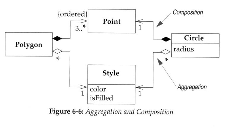
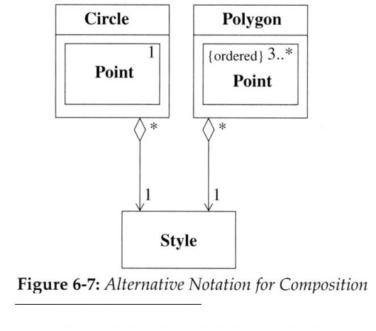
See Fowler, ch 5 (p. 68) for more details: e.g., {ordered} is a representation constraint
http://www.cse.lehigh.edu/~glennb/oose/figs/agg6-6.jpg, agg6-7
Arrow denotes navigability (e.g., Polygon and Circle refer to Point but not vice versa)
A black-filled diamond denotes a composition (a part, unique to this whole--see p. 86)
A white-empty diamond denotes an aggregation (a part, but not unique to this whole)
E.g., A Point may appear in only one Polygon or Circle but a Style could appear in both
3) Subject represented by larger gray boxes containing classes
E.g., one box is HIC (human interaction component) and second is PDC (problem domain)
UML has packages, denoted by box with smaller box on top, in separate diagrams
Note that this is decomposition (breaking a problem down) but not functional decomposition
Provide larger granularity for design and implementation, prior to integration
Seems to me that subject/package design is a design rather than an analysis activity
4) Attributes (properties, fields) and 5) services (behaviors, methods, UML operations)
Coad & Yourdon and UML have similar structure within classes
Attributes (in middle section) could be represented as associations or whole/part relations
Typically, attributes are simple types and single-valued
UML lets you include information about default values and visibility (+,-,#),
(but I recommend you hold off on these details until design stage)
Services or URL operations (at bottom section) represent methods or procedures
Again, UML has a bit more notation, for information about default values and visibility
E.g., + balanceOn(date:Date): Money
Again, I recommend you hold off on these details until design
Modeling dynamic behaviors with sequence and collaboration diagrams
(See Fowler, chapter 5)
Class diagrams describe static relationships between classes,
but what about modeling dynamic behavior?
Interaction diagrams model how groups of object collaborate in some behavior
Typically, an interaction diagram captures the behavior of a single use case
Example use case (http://www.cse.lehigh.edu/~glennb/oose/figs/UseCaseOrderEntry.htm):
An Order Entry window sends a “prepare” message to an Order
Order sends “prepare” to each Order Line on the Order
Each Order Line checks the given Stock Item: if true, remove Stock Item and deliver
If Stock Item falls below reorder level, then Stock Item requests reorder
Sequence diagram (http://www.cse.lehigh.edu/~glennb/oose/figs/seq5-1.jpg):
Vertical line is called an object’s lifeline, representing an object’s life during interaction
Object deletion denoted by X, ending a lifeline
Horizontal arrow is a message between two objects
Order of messages sequences top to bottom
Messages labeled with message name, optionally arguments and control information
Control information, in brackets, may express conditions, such as [hasStock], or iteration
Returns (dashed lines) are optional; use them to add clarity
Sequence diagrams can also represent concurrent processes:
UML 1 models asynchronous messages as horizontal lines with half arrow heads
UML 2 makes this distinction by not filling an arrowhead
Fowler prefers older notation. Why? Which do you prefer?
After setting up Transaction Coordinator, invoke concurrent Transaction Checkers
If a check fails, kill all the Transaction Checker processes
Note use of comments in margin – When is this a good idea? for documentary purposes
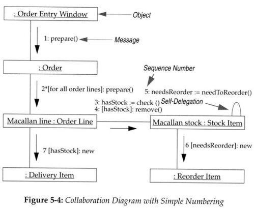
Collaboration diagram is a second way to model interactions of objects
Objects are rectangular icons, e.g., Order Entry Window, Order, etc.
Messages are arrows between icons, e.g., prepare()
Numbers on messages indicate sequence; also spatial layout helps show flow
Which do you prefer: sequence or collaboration diagrams?
Fowler now admits he doesn’t use collaboration diagrams, demoting them to ch 15
Interaction diagrams show flow clearly, but are awkward when modeling alternatives
UML notation for control logic has changed in UML 2, but Fowler isn’t impressed
Fowler recommends using CRC cards to begin modeling scenarios
Then document with UML sequence (or interaction) diagrams
Use sequence diagrams to show collaborations among many objects
Use state diagrams to show the behavior of a single object across many use cases
Tags: analysis requirements, an analysis, analysis, precede, object‑oriented, requirements, domain, design
- PROCEDURES FOR RESPONDING TO THE DEATH OF A FACULTY
- (BOARD NAME) MEETING MINUTES (DAY MONTH DATE YEAR) (BOARD
- SISTEMA DE EVALUACIÓN DEL DESEMPEÑO SERVIDORES PÚBLICOS DE LA
- LJUBLJANA 3 3 2009 GOSPOD MAG BLAŽ KAVČIČ PREDSEDNIK
- WYKONANIE ROBÓT BUDOWLANYCH ZMIERZAJĄCYCH DO ZAMONTOWANIA NA BUDYNKU ANTEN
- 27 APRIL 2008 NOTE TO EDITORS HOTEL SECTOR
- EGENERKLÆRING FOR MONITORERINGAUDIT I KLINISKE STUDIER VED AKERSHUS UNIVERSITETSSYKEHUS
- ORGANIZACE PRVNÍHO TÝDNE ŠKOLNÍHO ROKU 20152016 ŠKOLNÍ ROK 20152016
- SOCIEDAD ESPAÑOLA PARA EL ESTUDIO DE LOS ESTADOS UNIDOS
- SANTA FE “CUNA DE LA CONSTITUCIÓN NACIONAL” PROVINCIA
- CALLE MÚSICO JARQUE CUALLADÓ 9 46009 VALENCIA TELF96 346
- VATROGASNA ZAJEDNICA ISTARSKE ŽUPANIJE COMUNITA DEI VIGILI DEL FUOCO
- AGENDA DE SUPERVIVENCIA DE VERANO CONTENIDO PLAN DE VIDA
- NUEVO ENFOQUE DE THE COORDINATING CENTER PARA LA TRANSICIÓN
- AMERICAN LAND TITLE ASSOCIATION MINIMUM STANDARD DETAIL REQUIREMENTS AMERICAN
- 20212022 EĞİTİM YILI GÜZ YARIYILINDA MATEMATİK BÖLÜMÜNDE OKUTULAN LİSANS
- BTK ÍTÉLŐTÁBLAI HATÁROZATOK 51 ÍTÉLŐTÁBLAI HATÁROZATOK 2004 – 2013
- KOMMUNE KUJALLEQ DET KAN BETALE SIG MED EN LUFTHAVN
- BIZNESPLAN W RAMACH PROJEKTU „GRUDZIĄDZKI START W BIZNESIE” W
- EL JUICIO VERBAL TEMA 33 EL JUICIO VERBAL (ESQUEMA)
- AJUNTAMENT DE MATARÓ PLEC DE CLÀUSULES ADMINISTRATIVES PARTICULARS PER
- « ENTÊTE CABINET CONSEIL » VILLE………………… DATE………………………… « NOM
- ESPONJA DE FIBRINA TACHOSIL® CIRUGÍA PEDIÁTRICA INFORME PARA LA
- DEFICIENCIAS VISUALES Y PSICOMOTRICIDAD TEORÍA Y PRACTICA PILAR ARNAIZ
- RESUMEN COMUNICACIÓN XV JORNADAS DE INVESTIGACIÓN EN LA ZONA
- MODELO 81 LIQUIDACIÓN FINAL DE OBRA EJECUTADA (MODELO
- LIVING ENVIRONMENT COURSE SYLLABUS INSTRUCTOR MR SMEAL EMAIL NSMEALNFSCHOOLSNET
- DIRECTOR D’ESTIU (CAP DE LLEURE) ENTITAT DE PROMOCIÓ CULTURAL
- EJERCICIOS DE RADICALES 1 EXTRAER FACTORES A B 2
- BOTTOM UP PROIEKTUAK ONARTZEKO FINANTZATZEKO ETA EBALUATZEKO OINARRIAK 2014KO
ZNAK SPRAWY BFZ4073PR92014 ZAŁĄCZNIK NR 41 DO SIWZ ZESTAWIENIE
 LISTA DZIECI PRZYJĘTYCH DO PUNKTU PRZEDSZKOLNEGO „KRAINA UŚMIECHU” W
LA LUNA ROJA ROBERTO ARLT (19001942) NADA LO ANUNCIABA
7 CEDEFOP SEMINAR ON INDIVIDUAL LEARNING ACCOUNTS AN INCENTIVE
 “HELMUGA MOZART” WEB QUESTA EGILEA NEREA TERÁN ( ABANDO
 EDITORIAL GUIDELINES FOR DOSSIER EDITORS THE EEL WEBSITE HAS
COLEGIO OFICIAL DE ARQUITECTOS DE GRANADA COMUNICACIÓN DE ENCARGO
RENTA ACTUAL LEY SOBRE IMPUESTO A LA ART
NZQA UNIT STANDARD 23986 VERSION 3 PAGE 2 OF
ANEXO IV DECLARAÇÃO RELATIVA À TRABALHO DE MENORES
CELKOVÁ PROHLÍDKA SEŘÍZENÍ – 390 KČ CELOODPRUŽENÉ KOLO 590
GRAND TOUR OF ROMANIA 12 DAYS 11
ZAŁĄCZNIK NR 1 WYKAZ ZUŻYTYCH I ZBĘDNYCH SKŁADNIKÓW MAJĄTKU
PASOS A SEGUIR PARA TRAMITAR UNA LICENCIA APERTURA
 COMUNICADO DE PRENSA CONCEJAL JAVIER PALACIO MEJÍA “NO MAS
GEMİ ACENTELERİ EĞİTİM YÖNERGESİ BİRİNCİ BÖLÜM GENEL HÜKÜMLER AMAÇ
 FROBOMIND PROPOSING A CONCEPTUAL ARCHITECTURE FOR AGRICULTURAL FIELD ROBOT
 CHANGE REQUEST PROJECT NAME CHANGE NUMBER REQUESTED BY
TITEL SPRÅKSTIMULERING I GRUPP NAMN ANNSOFIE TALEMAN OCH JENNIFER
 CESTA NA ROGLO 13 B 3214 ZREČE TEL 03
