RADIO SHACK HTX100 MICROPHONE AMPLIFIER ANALYSIS AND IMPROVEMENT
0 Rag031e International Telecommunication Union Radiocommunication Advisory0 RAG081E RADIOCOMMUNICATION ADVISORY GROUP GENEVA 1315
14 8BXXXE INTERNATIONAL TELECOMMUNICATION UNION RADIOCOMMUNICATION STUDY
3 RADIOCOMMUNICATION STUDY GROUPS SOURCE DOCUMENT 4CTEMP42(REV1)
6 7BL13E INTERNATIONAL TELECOMMUNICATION UNION RADIOCOMMUNICATION STUDY
9 7D129 (ANNEX 3)E RADIOCOMMUNICATION STUDY GROUPS
Radio Shack HTX-100 Microphone Amplifier analysis and improvement
Radio Shack HTX-100 Microphone Amplifier analysis and improvement
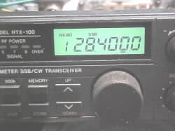
Equipment: Radio Shack HTX-100 10 Meter SSB/CW Transceiver
Catalog
Number: 19-1101
On-air reports of muffled audio coupled with off-air confirmation of same led to a technical investigation of the transmit audio response characteristics of this radio. A cursory review of a few of the 'hacks' on the web (like a cap across the Mic Att stage) on how to 'cure' or mitigate this muffled audio response spurred me on to write this web page in order to point out EXACTLY what is taking place inside the HTX-100 to cause 'muffled' transmit audio AND what a proper 'cure' involves.
It also appeared, during testing, that the microphone was extremely sensitive; verily, this was born out during testing and the "A"-half of opamp IC3 was found to be operating very near open-loop gain!
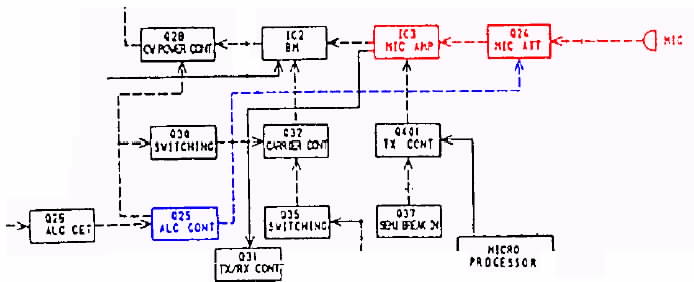
Block Diagram
Below is a block diagram with the circuitry under scrutiny shown in red. In particular, the Microphone Attenuator Q24 (driven by ALC Control Q25) and the Mic Amplifier using one half of IC3 are the subjects of this webpage. Part of the "ALC" (Automatic Level Control) circuitry (shown in blue) as well as other circuitry are shown as they 'surround' and interface with circuity around, in, near, or share an opamp in IC3 with the Mic amp et al.
The Mic Amplifier, using the "A" half Opamp in IC3 delivers an amplified audio signal to the "Gilbert cell" active component Balanced Mixer, IC2. (Barrie Gilbert on the invention of "The Gilbert Cell".) The output of IC2 is routed through FT2/FL205; THIS is the filter that makes this radio.
FT2/FL205 is the *sharp* filter that defines the receive characteristis of the HTX100 as well as the ultimate transmit bandwidth (assuming subsequent RF stages are operated linearly and not into 'clipping'). Shortcomings in the selected component values of the Microphone Amplifier IC3, however, serve to severely limit the highs above 1500 Hz (as will be shown further below).
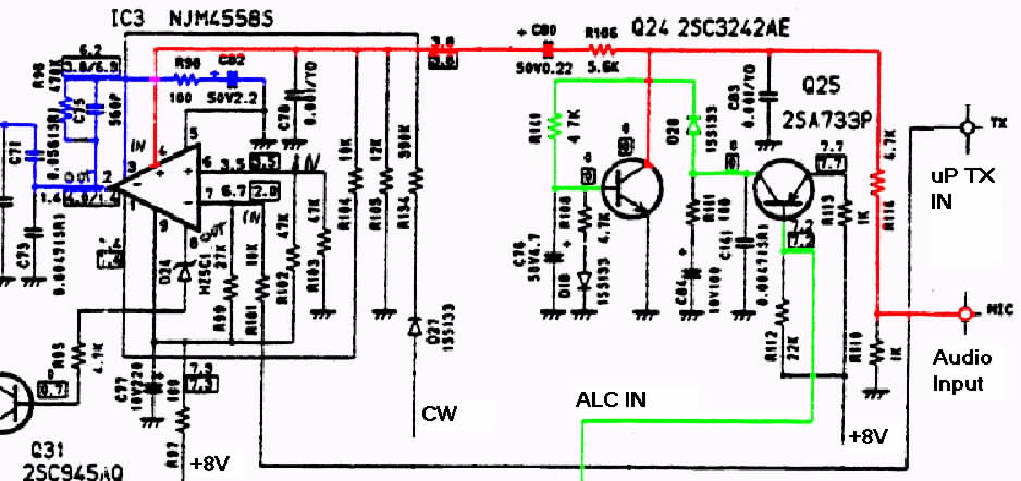
Electronic Schematic Diagram
The following schematic fragment was excerpted from a scanned copy of the HTX-100 Service Manual found on the web here.
In the following schematic fragment, the following color conventions were chosen to highlight key functions in the transmit microphone and ALC audio circuitry:
- Red, Audio/Mic circuit input
- Blue, Opamp Output and feedback network
- Green, ALC circuit
Note that the majority of the resistors appearing in that badly drawn and confusing schematic are for bias; that is, they merely set the DC operating point of the two opamps that are resident in the NJM4558S 9 pin in-line package. Note also that only one of the two opamps inside the NJM4558S package device is used as an audio amplifier, the other opamp is used as a simple comparator/level-shifter in the transmit keying circuit.
NJM4558/RC4558 Opamp
Below is the pinout of the NJM4558 IC. Note that this device is a member of the 4558 family of opamps from such manufacturers as Raytheon and Fairchild as an "RC4558" which is described as a "Dual High-Gain Operational Amplifier".
The RC4558 integrated circuit is a dual high-gain operational amplifier internally compensated and constructed on a single silicon IC using an advanced epitaxial process. Combining the features of the 741 with the close parameter matching and tracking of a dual device on a monolithic chip results in unique performance characteristics. Excellent channel separation allows the use of this dual device in dense single 741 operational amplifier applications.
Note that the NJM4558 in the "S" package has *two* Vcc pins; pin 1 and pin 9. In the annotated HTX-100 schematic fragment above, R104 (along with R105) provides 'bias'/sets that opamp's DC voltage operating point (via pin 4) by applying a DC voltage to the non-inverting input of the "A" half of opamp IC3, and furthermore, this connection is shown to be *through* IC3 to the +8V supply!

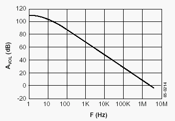
NJM4558/RC4558 Opamp - Open loop frequency response
Compare the open loop gain in the chart at around 2 to 3 KHz (around 60 dB) to the gain of an NJM4558 in the actual Microphone Amplifier circuit as measured further below. It appears the 4558 in this app was running very near open loop, save for the negative feedback contributed by the 560 pF capacitor.
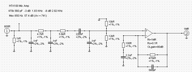
Microphone Amplifier - AC Circuit analysis
The following schematic was entered to determine the AC characteristics of the HTX-100's microphone/transmit audio amplifier frequency response.
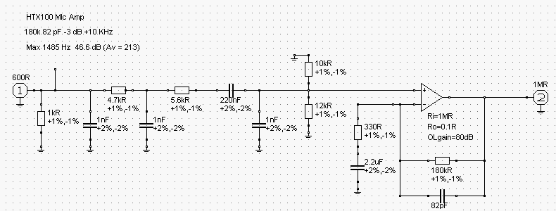
The following schematic was entered to determine the AC characteristics of the proposed improvements to the HTX-100's microphone/transmit audio amplifier; note that two resistor values and one capacitor value were changed per a chart to be found further down below.
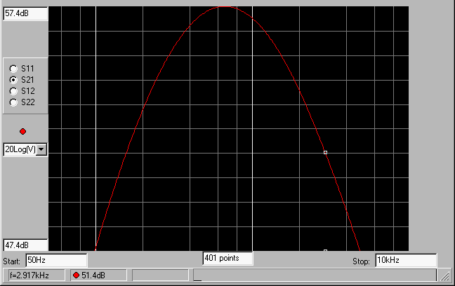
Analysis of existing circuit
- Measured Gain (at peak): 56 dB (Av = 630)
- Measured frequency response:
-6 dB 165 Hz
Peak 530 Hz
-6 dB 1550 Hz
-10 dB 2500 Hz
- Modeled frequency response
Circuit value changes to improve high frequency response and modeling of new circuit values as shown below:
Reference Old New
Designator Value Value
---------- ----- ----
R96 470K 180K
R98 100 330
C75 560pF 82pF
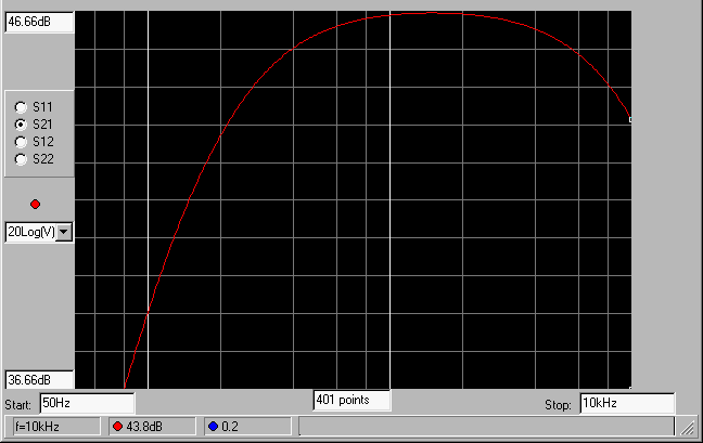
- Measured Gain (at peak): 45.3 dB (Av = 184)
- Measured frequency response:
-6 dB 140 Hz
-3 dB 250 Hz
Peak 1250 Hz
-6 dB 10 KHz
-10 dB N/A
- Modeled frequency response:
On-air testing
In-circuit test of new values; in situ voice quality observation by other operators.
- Indications are that the effort expended resulted in improvements, good reports are now had.
Parts location - changing the components
The area in blue below contains the Microphone Amplifier and Mic Attenuator/ALC circuit components. The area in blue is shown in more detail in an excerpt further below.
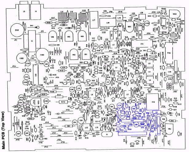
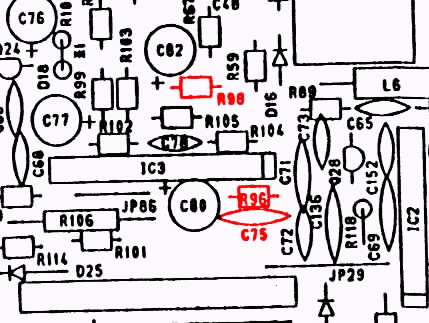
The components outlined in red are the components changed out to improve microphone amplifier frequency response. To gain access to the rear of the HTX100 Main Board and change these components the PLL Assembly, located under the Main Board, will have to be temporarily removed; this is an easy task involving four screws and three connectors: two multi-wire connectors and one coax connection.
After the PLL Assembly is removed the rear of the Main Board is easily accessed to allow desoldering and removal of the orginal components and installation of the new components.
![]()
![]()
Link summary:
Open-loop gain - practically, the gain is so high that the output will be driven to Vcc or Vee for any appreciable difference between the inverting (-) and non-inverting (+) inputs.
Negative feedback or closed loop gain - feedback is used to 'stabilize' or set the gain to a useful, fixed value that is relatively independent of the opamp's open-loop (and device fabrication and process yield dependent) gain figure.
The "Gilbert cell" mixer.
Barrie Gilbert on the invention of "The Gilbert Cell"
Over the years, I have talked to several people who have owned both the HR2510 and the HTX100. The comment inevitably comes up that the HTX100 has a 'better receiver' that the HR2510. But how can this be? Everyone knows that the 2510 and the HTX have virtually identical RF sections.
When I finally managed to acquire an HTX100 last year, I decided to investigate to try and prove or disprove this notion once and for all. Examination of the schematics for both radios showed that the RF sections were indeed almost identical. I reasoned that the 2510, being an 'allmode' radio with AM included, may use the common CB radio design practice of having a wider 'compromise' IF crystal filter to improve the RX audio response on AM. The center frequency of both filters is 10.695 MHz, so assuming that the carrier oscillator signal is placed on the slope of the filter, a check of the carrier oscillator alignment frequency for USB should tell us the approximate bandwidth of the filter. Sure enough, the USB carrier oscillator frequency is different in the two radios! Shown below is a chart of the carrier oscillator frequencies for both rigs, with a LSB value extrapolated for the HTX100.
As can be seen from the graph, the HTX filter is indeed significantly narrower than the 2510 filter. (Visit this site to view graph.)
HTX-100 Service Manual available here.
4558 opamp history discussed about half-way down in this thread.
What exactly is an Op-Amp?
Intro:
The term 'op-amp' was originally used to describe a chain of high performance dc amplifiers that was used as a basis for the analog type computers of long ago. The very high gain op-amp IC's our days uses external feedback networks to control responses. The op-amp without any external devices is called 'open-loop' mode, refering actually to the so-called 'ideal' operational amplifier with infinite open-loop gain, input resistance, bandwidth and a zero output resistance.
However, in practice no op-amp can meet these ideal characteristics. And as you will see, a little later on, there is no such thing as an ideal op-amp. Since the LM741/NE741/µA741 Op-Amps are the most popular one, this tutorial is direct associated with this particular type. Nowadays the 741 is a frequency compensated device.
Let's go back in time a bit and see how this device was developed.
The term "operational amplifier" goes all the way back to about 1943 where this name was mentioned in a paper written by John R. Ragazzinni with the title "Analysis of Problems in Dynamics" and also covered the work of technical aid George A. Philbrick. The paper, which was defined to the work of the U.S. National Defense Research Council, was published by the IRE in May 1947 and is considered a classic in electronics.
The very first series of modular solid-state op-amps were introduced by Burr-Brown Research Corporation and G.A. Philbrick Researches Inc. in 1962. The op-amp has been a workhorse of linear systems ever since.
9 NONRADIOACTIVE IN SITU HYBRIDIZATION OF PARAFFIN
AVIS DE COURSE VOILE RADIOCOMMANDEE 28°
Getting Practical Work Into the Teaching of Radioactivity
Tags: amplifier analysis, operational amplifier, improvement, radio, analysis, microphone, shack, htx100, amplifier
- OPENING OF THE EXHIBITION OF ILLUSTRATIONS BY RENÁTA FUČÍKOVÁ
- ZAKON O PUTNIM ISPRAVAMA HRVATSKIH DRŽAVLJANA (UREDNIČKI PROČIŠĆENI
- ERKLÆRING OM AUTORISATION TIL ØKOLOGI SKAL KUN
- CATHOLIC RELIEF SERVICES (CRS) RECRUITMENT STRATEGY (INTERNAL DOCUMENT) THE
- NEWS RELEASE A CER EUROPE SA VIA CANTONALE
- MUSUH DALAM SELIMUT KARYA ERI PRAMESTININGTYAS XD11 WAKTU
- CORTE SUPREMA DE JUSTICIA INFORME ANUAL DE NOTARIOS
- 18 MAJOR CLASSIFICATION BIOLOGICAL SCIENCES MINOR CLASSIFICATION PSYCHOLOGY NEWBORN
- MICROCHIP LIBRARIES FOR APPLICATIONS ARCHIVES MICROCHIP LIBRARIES FOR APPLICATIONS
- PAGE 4 OF 4 ANDROID SMART PHONE OPERATED WEIGHING
- 45 UOT 33996562 (4)(5) “BAKITBİLİSİQARS” LAYİHƏSİ AVROPAASIYA ARASI DAŞINMALARININ
- ATAJOS BÁSICO WINDOWS + E (DE EXPLORER) ICONO DE
- PRILOG 1 OPĆI UVJETI UGOVORA O NABAVI KOJE FINANCIRA
- WNIOSEK O UZNANIE ZAKŁADU ZA WOLNY OD ZAKAŻENIA 1
- 20181031 TÄBYALLIANSEN POLITISK INRIKTNING FÖR TÄBY KOMMUN UNDER
- CLASSICAL ENCRYPTION TECHNIQUES PLAINTEXT ORIGINAL MESSAGE CIPHERTEXT – CODED
- PHYSICS 1 ROBAK LIGHT AND MATTER TRANSPARENT – MATERIAL
- UMOWA NR FIRMA Z SIEDZIBĄ REGON
- BASES REGULADORAS DE LOS PREMIOS CERMIES 2015 EL COMITÉ
- SECRETARIA DE SALUD EDUCACION CULTURA Y DEPORTE ANEXO EDICTO
- AGENDA RULES REVIEW COMMISSION THURSDAY JANUARY 20 2011 900
- MASSENSPEKTROMETER 1 GCMS GERÄT (SSQ 710) (BIS MZ
- UTVIT100 – ARBEIDSKRAV TIL SEMINARET PEDAGOGISK FORSKNINGSINSTITUTT FORVENTINGER TIL
- PRIJAVA PONUDNIKA STORITEV ZA ZAČASNO OPRAVLJANJE REGULIRANEGA POKLICA OZIROMA
- 20190522 DNR 15783 BERÖRDA SAKÄGARE LÄNSSTYRELSEN I JÄMTLANDS LÄN
- AUTORIZACIÓN PARA EL REGISTRO DE MENORES DE EDAD DOCUMENTO
- URED VLADE REPUBLIKE HRVATSKE ZA UDRUGE SA SJEDIŠTEM U
- PROCESO CONTABLE DE LAS AMORTIZACIONES TÉCNICAS EJEMPLO A PRINCIPIOS
- ARKIVBESKRIVNING MINNESLISTA EN FULLSTÄNDIG GENOMGÅNG AV ARKIVET HAR
- ARTIKEL FÜR IM FINAL STAND 20 JUNI 2008 KREIDETAFEL
NA TEMELJU ČLANKA 25 STATUTA GRADSKE KNJIŽNICE I ČITAONICE
 VOLOS DEVELOPMENT COMPANY (ANEVO SA) IS A NEW DEVELOPMENT
 HIGH TEMPERATURE ISOTHERMAL OXIDATION BEHAVIOUR OF AN OXIDE DISPERSION
CURSO DE POSGRADO ÁLGEBRA LINEAL Y SUS APLICACIONES PROFESORES
 LOGO EMPRESAENTIDAD CONVENIO DE COLABORACIÓN ENTRE LA UNIVERSITAT POLITÈCNICA
 THEATRE SHOWCASE FOLLOWING THE SUCCESSFUL 1ST YEARS EDITION
MATE HOUSING MINISTRY A MINISTRY OF MISSION AT THE
REPORT TITLE AND LINK TITLE III POLICY STATE
REGULAMIN POSTĘPOWANIA PRZY UDZIELANIU ZAMÓWIEŃ PUBLICZNYCH REGULAMIN OKREŚLA ZASADY
 G OBIERNO DEL ESTADO DE SAN LUIS POTOSÍ I
 1ª ETAPA ELEGIR UNA PREGUNTA GENERAL DETERMINAR EN QUÉ
PERFORMANCE COMPARISON IN SMES ABSTRACT THIS PAPER SEEKS TO
UNIQUE MINISTRIES REQUEST GUIDELINES FOR QUALIFICATION ON BACK MISSISSIPPI
 LES NUISANCES SONORES DE L’A 31 CERTAINS D’ENTRE VOUS
ДОДАТОК 12 ДО ПОЛОЖЕННЯ ПРО РЕЄСТРАЦІЮ ФІЗИЧНИХ ОСІБ У
 NEWBURYPORT PUBLIC SCHOOLS MEDICATION PROTOCOLS FOR NEWBURYPORT SCHOOL NURSES
LISTADO ESTABLECIMIENTOS BALNEARIOS BALNEARIO BAÑOS DE FITERO FITERO BALNEARIOS
UNIVERSIDAD AUTÓNOMA DE AGUASCALIENTES DIRECCIÓN GENERAL DE FINANZAS ACTA
 POR BORJA CASTROVIEJO (4º SORZANO) TE RECOMIENDO ESTE LIBRO
 LABORATORIO DE FÍSICA CON ORDENADOR STUDENT WORKBOOK EXPERIENCIA P05
