ME 410L – PRESSURIZED STEAM GENERATOR (PSG) INSTRUCTOR
ME 410L – PRESSURIZED STEAM GENERATOR (PSG) INSTRUCTOR
ME 410L – Pressurized Steam Generator (PSG) - Instructor: Reza Baghaei Lakeh
ME 410L – Pressurized Steam Generator (PSG) - Instructor: Reza Baghaei Lakeh
Thermal Science Laboratory
ME410L
Pressurized Steam Generator (PSG)
Instructor:
Reza Baghaei Lakeh
Fall 2010
Experimental Apparatus
The Armfield Saturation Pressure Apparatus has been designed to introduce students to how the temperature of water behaves at its boiling point with variation in the absolute pressure. Saturation curves can be obtained by the student and compared with published steam tables. The quality of steam exiting the apparatus can be determined using a throttling calorimeter connected at the point of discharge.
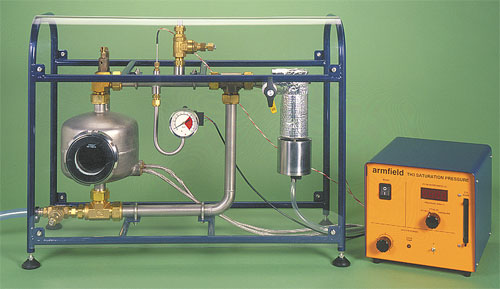
A bench top unit comprising a boiler vessel and pipe loop with a pressure relief valve to limit the operating pressure to 8 bar gauge. A sight glass on the front of the boiler allows the boiling patterns to be observed and a Bourdon type gauge indicates the pressure in the apparatus at all times for safe operation.
A throttling calorimeter mounted adjacent to the pipe loop allows the condition of the saturated steam to be determined by measuring the temperature of the steam following throttling to atmospheric pressure. Temperatures in the pipe loop and inside the throttling calorimeter are measured using PRT sensors and pressure in the loop is measured using an electronic pressure sensor. An electrical console houses the necessary electronics with current protection devices and an RCD for operator protection. A digital meter with selector switch displays all sensor measurements. The boiler is heated by a pair of 500 W electric heating elements with variable power control and over-temperature protection.
Objectives of the Experiment
> Observation of the patterns of boiling at the surface of the water
> Understanding saturation curves and the characteristics of a two phase fluid
> Understanding the origin and use of steam tables
> Using a throttling calorimeter to determine the quality of wet steam
Description of the Apparatus
The apparatus consists of a rectangular pipe loop incorporating a cylindrical boiler in one vertical limb. Pure water in the boiler is heated to its boiling point using a pair of cartridge heaters with variable power control. A sight glass on the front of the boiler allows the internal processes to be observed, namely boiling patterns at the surface of the water, and also allows the water level in the boiler to be monitored. Saturated steam leaving the top of the boiler passes around the pipe loop before condensing and returning to the base of the boiler for re-heating. The operating range of the boiler and loop is 0 to 7 bar gauge.
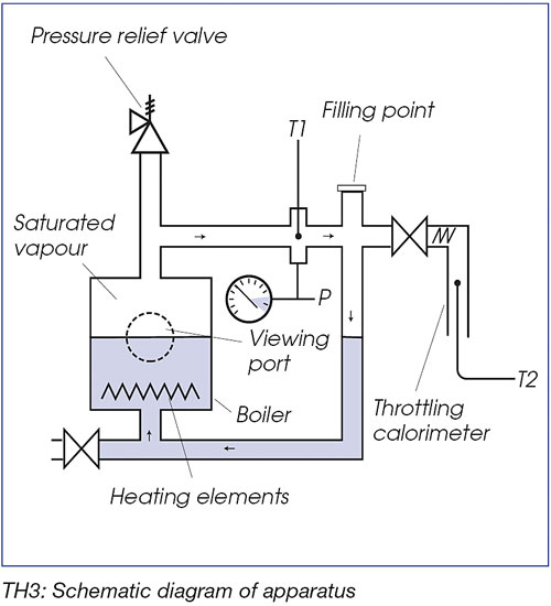
The top limb of the pipe loop incorporates a PRT temperature sensor and an electronic pressure sensor to measure the properties of the saturated steam. A filling point on the top limb allows the loop to be filled with pure water and allows all air to be vented safely before sealing the loop for pressurised measurements. A vapour offtake, with isolating valve, allows steam from within the loop to be passed through a throttling calorimeter, the purpose of which is to demonstrate how the dryness fraction of the saturated steam in the loop can be determined. The steam expands to atmospheric pressure as it is throttled and a second PRT temperature sensor measures the temperature of the steam following expansion.
Laboratory Procedure
Record the barometric pressure in the lab.
Check the area and make sure the apparatus and the stand are stable.
Identify the following elements: electric console, filler valve, filler pipe, drain valve, drain pipe, calorimeter, calorimeter valve, relief valve, and pressure gage and temperature sensors.
Check that the RCD and three circuit breakers on the rear of the console are all in the ON position.
Check that the main switch on the front of the console is switched off.
Check that the heater switch is off and the heater power control is set to minimum.
Check that the drain valve is closed using the tool supplied.
Check that the calorimeter isolating valve is closed – lever vertical.
Open the filler valve on the top of the apparatus using the tool supplied.
Using a funnel, slowly fill the system with pure water until the level reaches ¾ of the way up the sight glass on the front of the boiler. Approximately 1.75 liters of water will be required. Do not close the filler valve at this point.
Switch on the main power switch on the console. The digital display should be illuminated.
Use the selector switch to check that initial readings for PT100(1), PT100(2) and P are sensible. P should be approximately 0 kN/m2. The actual values for PT100(1) and PT(100(2) will depend on the ambient temperature but a typical reading will be 109 Ohms at 20°C.
Make sure that the isolating valve to calorimeter is closed. Then, switch on the heater and set the power control to maximum and allow the water to heat.
Four heating regimes can be visually observed through the sight glass. Make sure you can distinguish the regimes according to the theory section.
When the water is boiling with steam issuing from the filler line confirm that reading from PT100(1) is approximately 138 Ohms corresponding to a temperature of 100°C (Actual readings will depend on the atmospheric pressure). Then, close the filler valve. This will increase the pressure of the system.
DO NOT ATTEMPT TO OPEN THE FILLER OR DRAIN VALVES
WHEN THE SYSTEM IS PRESSURIZED!
Record the Pressure of the system and the value of PT100(1) in Table 1 every two minutes until the pressure is approximately 6 bar. (The relief valve will open if the pressure is increased more than 6 bar.)
When the pressure reaches the maximum (approximately 6 bar), open the isolating valve to the calorimeter. This will allow the pressurized steam to expand in a “constant enthalpy” process and leaves the cycle. PT100(2) measures the temperature of the leaving steam after the expansion in the calorimeter. Remember that the corresponding pressure of point 2 is approximately the barometric pressure.
Record the values of Pressure, PT100(1) and PT100(2) in Table 2 every Three minutes. Continue this step until the system is depressurized.
Leave the system to cool down and completely depressurize.
Open the drain valve and filler valves and drain the water from the apparatus.
Questions *
Explain the boiling regimes that you observed.
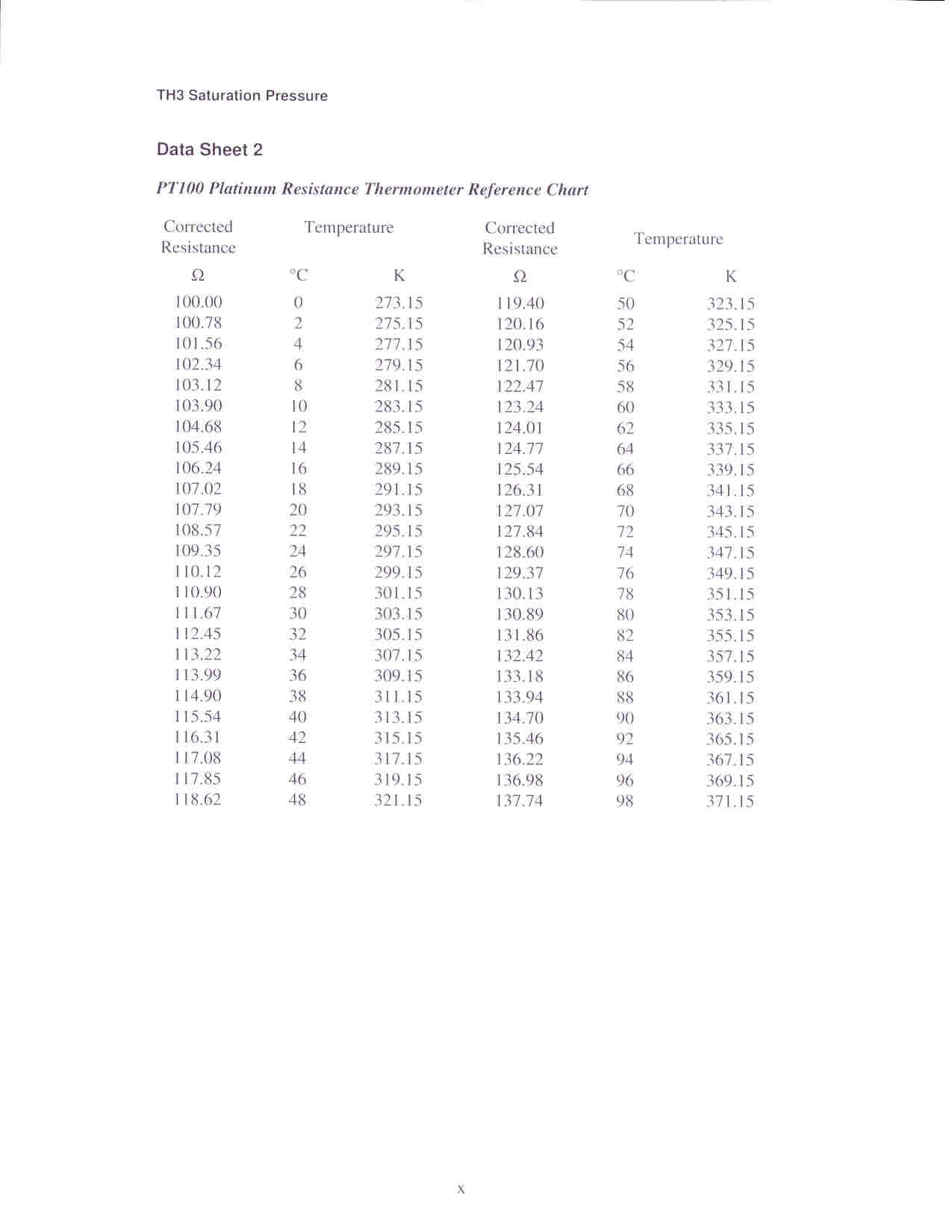
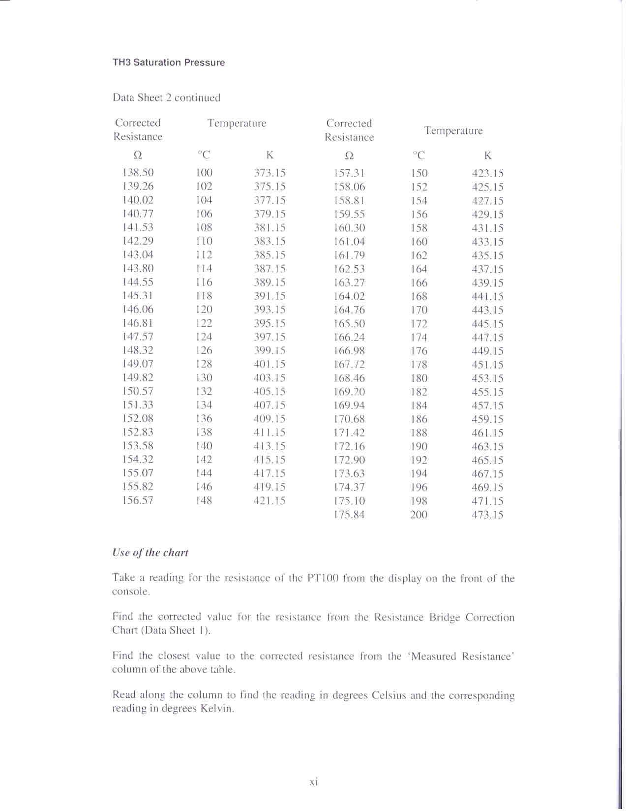
Using the provided conversion tables in Appendix, find the temperature values at each step and fill Tables 1 and 2. Make sure that you convert your Measured Resistance to Corrected Resistance and then find the corresponding Temperature.
What is the difference between gage pressure and absolute pressure? Which one would you use if you want to look up the thermo physical properties of steam in standard thermodynamic tables?
Convert the values of gage pressure to absolute pressure and fill the corresponding column in tables 1 and 2.
Plot the Pressure versus T1 from Table 1 and water saturation line (using thermodynamics tables) in one coordinate system and compare your results with theory.
How does the boiling temperature of water change with pressure? Does it agree with theory?
Write the first law of thermodynamics for the calorimeter and show that the steam undergoes a “constant enthalpy process” in this element. Your result should proof that h1 = h2 !
Calculate the quality of vapor in the system (point 1) by making use of the following equation and fill the corresponding column of Table 2. (The quality is the vapor content of a two phase flow. If you don’t remember what that is, you may want to consult your thermodynamics book)
![]()
Notice that h2 depends on barometric pressure (and NOT system pressure) and T2. On the other hand, hf and hfg depend on system absolute pressure only!
Why do the hf and hfg only depend on system absolute pressure? (Hint: Are saturation pressure and boiling temperature independent?)
Plot the vapor quality versus absolute pressure of the steam.
How does the steam flow quality change with pressure? Compare your results with theory.
* In a number of questions, you will need to do a lot of linear interpolations. You may want to program your calculator or excel sheet for simplification. If you are not doing a lot of interpolations, you may want to catch a different train!

Table 1
|
Time |
Gage
Pressure |
Absolute
Pressure |
PT100(1)
|
PT100(1)
|
T1 (°C) |
|
|
|
|
|
|
|
|
|
|
|
|
|
|
|
|
|
|
|
|
|
|
|
|
|
|
|
|
|
|
|
|
|
|
|
|
|
|
|
|
|
|
|
|
|
|
|
|
|
|
|
|
|
|
|
|
|
|
|
|
|
|
|
|
|
|
|
|
|
|
|
|
|
|
|
|
|
|
|
|
|
|
|
|
|
|
|
|
|
|
|
|
|
|
|
|
|
|
|
|
|
|
|
|
|
|
|
|
|
|
|
|
|
|
|
|
|
|
|
|
|
|
|
|
|
|
|
|
|
|
|
|
|
|
|
|
|
|
|
|
|
|
|
|
|
|
|
|
|
|
|
|
|
|
|
|
|
|
|
|
|
|
|
|
|
|
|
|
|
|
|
|
|
|
|
|
|
|
|
|
|
|
|
|
|
|
|
|
|
|
|
|
|
|
|
|
|
|
|
|
|
|
|
|
|
|
|
|
|
|
|
|
|
|
|
|
|
|
|
|
|
|
|
|
|
Time (min) |
Gage
Pressure |
Absolute
Pressure |
PT100(1)
|
PT100(1)
|
T1 (°C) |
PT100(2)
|
PT100(2)
|
T2 (°C) |
hf |
hfg |
h2 |
x1 |
|
|
|
|
|
|
|
|
|
|
|
|
|
|
|
|
|
|
|
|
|
|
|
|
|
|
|
|
|
|
|
|
|
|
|
|
|
|
|
|
|
|
|
|
|
|
|
|
|
|
|
|
|
|
|
|
|
|
|
|
|
|
|
|
|
|
|
|
|
|
|
|
|
|
|
|
|
|
|
|
|
|
|
|
|
|
|
|
|
|
|
|
|
|
|
|
|
|
|
|
|
|
|
|
|
|
|
|
|
|
|
|
|
|
|
|
|
|
|
|
|
|
|
|
|
|
|
|
|
|
|
|
|
|
|
|
|
|
|
|
|
|
|
|
|
|
|
|
|
|
|
|
|
|
|
|
|
|
|
|
|
|
|
|
|
|
|
|
|
|
|
|
|
|
|
|
|
|
|
|
|
|
|
|
|
|
|
|
|
|
|
|
|
|
|
|
|
|
|
|
|
|
|
|
|
|
|
|
|
|
|
|
|
|
|
|
|
|
|
|
|
|
|
|
|
|
|
|
|
|
|
|
|
|
|
|
|
|
|
|
|
|
|
|
|
|
|
|
|
|
|
|
|
|
|
|
|
|
|
|
|
|
|
|
|
|
|
|
|
|
|
|
|
|
|
|
|
|
|
|
|
|
|
|
|
|
|
|
|
|
|
|
|
|
|
|
|
|
|
|
|
|
|
|
|
|
|
|
|
|
|
|
|
|
|
|
|
|
|
|
|
|
|
|
|
|
|
|
|
|
|
|
|
|
|
|
|
|
|
|
|
|
|
|
|
|
|
|
|
|
Appendix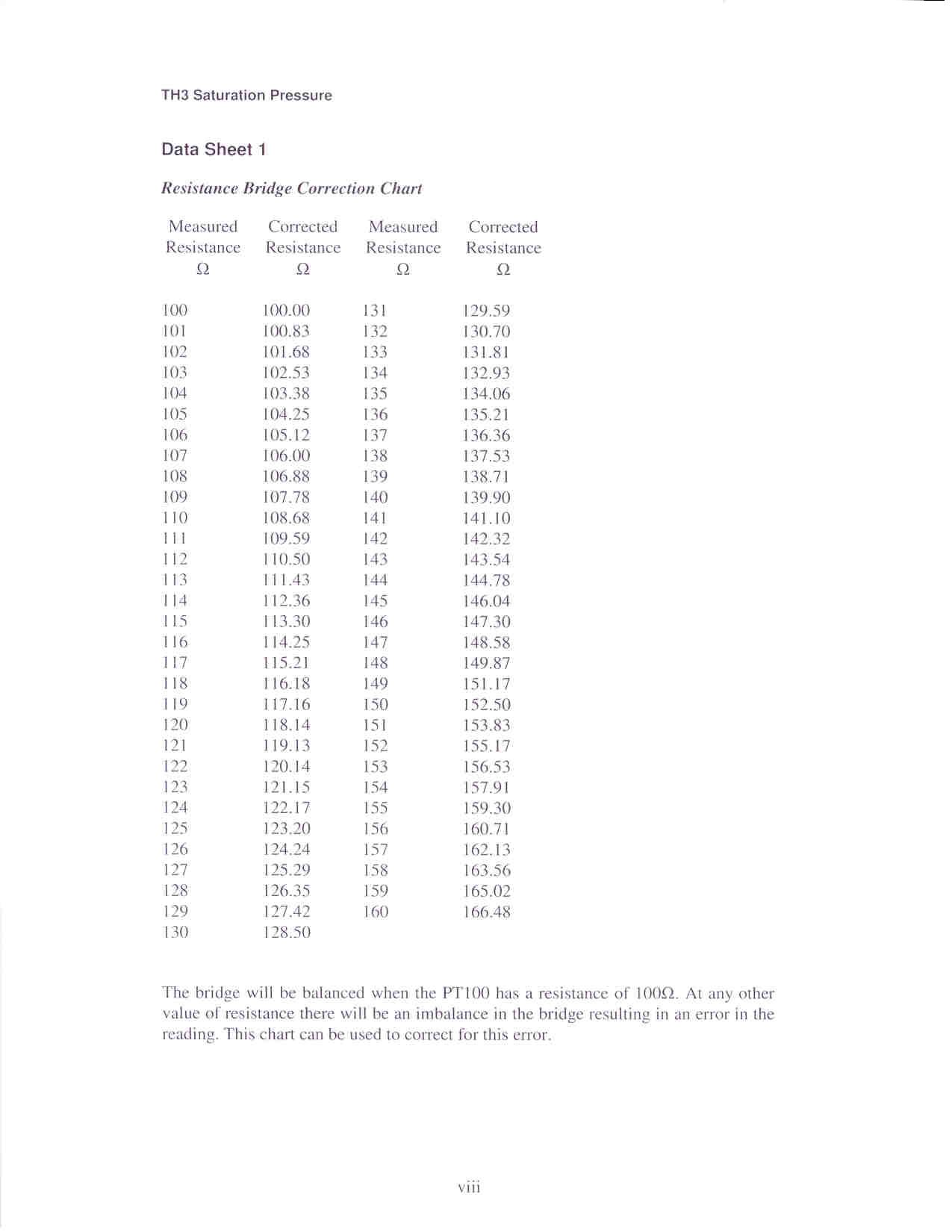
Tags: (psg) -, generator (psg), generator, steam, instructor, (psg), pressurized
- NAČRTOVANI TERMINI KOROŠKIH SLOVENCEV 2015 JANUAR 02 01 2015
- ZUSTIMMUNGSERKLÄRUNG DER BETROFFENEN NACHBARN LAUT TIROLER BAUORDNUNG 2018 –
- 10 JAHRE ARTE HOTEL KREMS – EINE ERFOLGSGESCHICHTE DAS
- ZKRATKY AKADEMICKÝCH TITULŮ A VOJENSKÝCH HODNOSTÍ 1
- 5 Hein Retter was hat die Geschichte des Jenaplans
- ROSENBERGER – EINE ERFOLGSGESCHICHTE ALS HANS ROSENBERGER SEN (+
- A TANULÓVAL SZEMBEN LEFOLYTATOT FEGYELMI ELJÁRÁS RÉSZLETES SZABÁLYAI 1
- ARTROSIS DE RODILLA 1 ¿QUÉ ES LA ARTROSIS DE
- 32006D0415 ODLUKA KOMISIJE OD 14 LIPNJA 2006 O ODREĐENIM
- IRAN’S INVISIBLE OPPORTUNITY FOR ENERGY AND SECURITY MODERN ENERGY
- DIE ESTERGESCHICHTE 1 TEIL KENNEN LERNEN DER FIGUR ESTER
- MISS NORTH ALABAMA OUTSTANDING TEEN PAGEANT NORTH ALABAMA’S OUTSTANDING
- INDIREKTE REDE 1 WANN WIRD DIE INDIREKTE REDE VERWENDET?
- THE BIKE DUMP WORKSHOP 5 – BOTTOM BRACKETS THERE
- am Rande Bemerkt Beobachtungen aus le Mans
- TECHNICAL DATA SHEET NO 225 VERSION31ST OCT 2001 PAGE
- ÁREA BASES ESPECÍFICAS QUE HAN DE REGIR LA CONVOCATORIA
- 100 JAHRE KREISVERBAND ESSLINGEN DER KLEINTIERZÜCHTER E V ALS
- PROGRAMA DE APOYO A LAS CULTURAS MUNICIPALES Y COMUNITARIAS
- Restraint of Molded pvc Fittings on ips od pvc
- DJECO TIP TOP CLAP CSELEKVÉS MEMÓRIA DJ05120 AJÁNLOTT
- Ley%20de%20Tr%C3%A1nsito%20y%20Transporte%20del%20Estado%20de%20Coahuila%20de%20Zaragoza
- Tomás Kismajor Traductor Reconocido por la Autoridad
- REFERAT FRÅ OPPSTARTSMØTE PROSJEKT MØTEREFERAT VEDK REGULERINGSPLANARBEID FOR GNR
- ACTO DE DETALLAR QUE ACTIVIDADES HAY QUE HACER EN
- CIRA GOESR RISK REDUCTION PROJECT MILESTONES 20032006 LAST UPDATED
- PROGRAMA DE CURSO NOMBRE DEL CURSO IMPACTO
- ACTION REQUEST FORM DISTRICT NO CEI CONTRACT DISTRICT
- Sample Manuscript as a Guide for Submission to aip
- REFUTA OEA QUEJAS DE ONGS PIDIÓ DEJAR TRABAJAR A
 SOCIOLOGICAL THEME WELSH LANGUAGE DATA SOURCE NATIONAL STATISTICS (HTTPWWWSTATISTICSGOVUK)
INFORMATIONSRECHERCHE UND –VERARBEITUNG BEWERTUNG SEMINARSITZUNG 1 ERARBEITUNG DER KRITERIEN
 NOTES BY TONY HODGSON MAY 2008 REFLECTIONS ON THE
 2016 M VASARIO 9 D (ANTRADIENĮ) 14 VAL (P
FERTILIZACION POTASICA FOLIAR Y EDAFICA DEL CULTIVO CEBOLLA HUGO
CONVENCION DE LAS NACIONES UNIDAS CONTRA EL TRAFICO ILICITO
 CE523 ASSIGNMENT 6 SOLUTIONS 1 SEAWATER IS TO BE
 UNEPCBDICCP19 PAGE 0 CBD CONVENTION ON BIOLOGICAL DIVERSITY DISTR
 HUD LOGO HOME PRESS ROOM PRESS
MASSENSPEKTROMETER 1 GCMS GERÄT (SSQ 710) (BIS MZ
54108SCIENCE OF LIGHT AND COLOR SPRING 2006 54108SCIENCE OF
CALIFORNIA MARITIME ACADEMY APPLICATION FOR SABBATICAL LEAVE 1 NAME
ACTS OF PARLIAMENT FORMAT COUNTRY NAME OF ACT NAME
 PO ECONOMIE VOLGENS DE OPDRACHT TIJDENS 6C 2002
PROPOSED CHANGES TO EALING COUNCIL’S HOUSING ALLOCATIONS POLICIES NOW
SAĞLIK KURULUŞU TIBBİ ATIK YÖNETİM PLANI FORMATI IGENEL BİLGİLER
 S UPLEMENT DO DYPLOMU – WYJAŚNIENIA AKTUALIZACJA NA DZIEŃ
7 PSICOANÁLISIS FREUD (CÁTEDRA II) PROFESOR TITULAR REGULAR DAVID
 HRVATSKI BOKSAČKI SAVEZ IX POJEDINAČNO BOKSAČKO PRVENSTVO HRVATSKE JUNIORKE
TRENINK VIDENI AURY NAPSANO ROBERTEM BRUCEM VOLNE PRELOZENO SNOPEM
