IFU FOR NUMERIS® TETHERED COAGULATION SYSTEM WITH VISITRAX®
IFU FOR NUMERIS® TETHERED COAGULATION SYSTEM WITH VISITRAX®
[LOGO]
IFU for Numeris® Tethered Coagulation System with VisiTrax® |
LBL-1774-US Rev. E |

Instructions for Use
for the
Numeris® Tethered Coagulation System
with VisiTrax®
AtriCure Incorporated
7555 Innovation Way
Mason, Ohio 45040 USA
Customer Service:
1-866-349-2342 (toll free)
1-513-755-4100 (phone)
Caution: Federal (U.S.) law restricts this device to sale by or on the order of a physician.
IFU for Coagulation Kit
LBL-1774-US Rev. E
Instructions for Use
![]() CAUTION:
Restricted
to use during procedures involving coagulation of cardiac tissue.
CAUTION:
Restricted
to use during procedures involving coagulation of cardiac tissue.
Product Description
Components of the Coagulation System:
Numeris® Tethered Coagulation System with VisiTrax® Device (sterile, for single-use only) – multiple formats include:
|
CS-1201 Coagulation Device, 1cm, |
CS-1202 Coagulation Device, 2cm, |
|
CS-1203 Coagulation Device, 3cm, or |
CS-1205 Coagulation Device, 5cm |
ACCESSORIES PROVIDED SEPARATELY:
CS-3000 RF Generator plus accessories, non-sterile, reusable (under separate IFU)
CS-2000 Coagulation Extension Cable (under separate IFU)
The Numeris® Tethered Coagulation Device with VisiTrax® is not made with natural rubber latex and are PVC-free.
Product Features
Figure 1. General Coagulation Device Key Features |
|
|
|
(1) Handle; (2) Vacuum Port; (3) Unused Port; (4) RF Connection; (5) Perfusion Port; (6) Stopcock; (7) Graduated Fitting to Vacuum Tubing; (8) Strain Relief; (9) Main Body; (10) Distal Shell; (11) Flexible Electrode; (12) Tether; (13) Insulative Covering; (14) Spine; (15) Vacuum Lumen; (16) Locator Arrows (1cm spacing) |

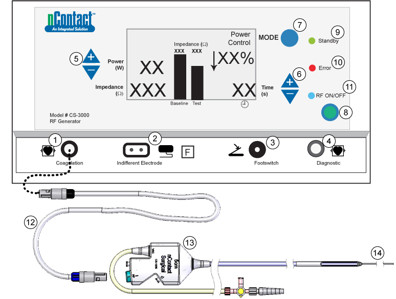
Figure 2. Connecting Device to Generator |
|
|
|
(1) Coagulation Device Connection; (2) Indifferent, dispersive electrode Connection; (3) Footswitch Connection; (4) Diagnostic device Connection; (5) Power Adjustment; (6) Time Adjustments; (7) Mode button; (8) RF ON/OFF button; (9) Standby Mode LED; (10) Error LED; (11) RF LED; (12) RF Extension Cable; (13) Handle; 14) Tether; |
Indications:
The Coagulation System is intended for the coagulation of cardiac tissue using radiofrequency (RF) energy during open-chest cardiac surgery.
Contraindications:
Patients with presence of left atrial thrombus, a systemic infection, active endocarditic, or another infection local to the surgical site at the time of surgery.
 Warnings
and Precautions:
Warnings
and Precautions:
Care should be taken to ensure that the device is not in contact with tissue that is not going to be coagulated (e.g. vascular and nerve tissue), in order to avoid inadvertent tissue damage.
Avoid contact with other surgical instruments, staples or other objects while coagulating. Inadvertent contact with objects while coagulating could lead to conduction of RF energy or heat and unintentional coagulation of tissues in contact with those objects.
The device is provided sterile and is intended for single patient use only. Do not reprocess or reuse. Reuse can cause damage to device, patient injury and/or the communication of infectious disease(s) from one patient to another.
The coils on the distal end of the device must be kept clean of coagulum during surgery to avoid loss of power. Do not clean coagulum off the electrode of the device with an abrasive cleaner or electrosurgical tip cleaner. The electrodes could be damaged, resulting in device failure.
If the device is used near a pacemaker, a potential hazard exists due to possible interference with the action of the pacemaker and potential damage to the pacemaker. A pacemaker in a patient undergoing any surgery with RF energy must be turned off before applying RF energy.
Implantable cardioverter / defibrillators can also be adversely affected by RF signals.
Interference produced by the operation of high-frequency surgical equipment may adversely affect the operation of other electronic medical equipment such as monitors and imaging systems. This can be minimized or resolved by rearranging monitoring device cables so they do not overlap the Coagulation System cables.
The use and proper placement of an Indifferent Electrode is a key element in the safe and effective use of electrosurgery, particularly in the prevention of patient burns. Ensure entire area of electrode is reliably attached to the patient’s body.
To avoid unintentional coagulation, care should be taken to ensure overlapping structures are separated and thermally isolated when anatomy allows.
Inspect the device and packaging prior to use. If any breach of the packaging is found the sterility of the product cannot be ensured. Do not use product if breach is found.
While the distal portion of the device is designed to be malleable to conform to the anatomy of the area to be coagulated, excessive manipulation, rough shaping or forcing the movement of the device may damage or deform the distal end and cause potential patient harm.
Care should be taken when handling the distal end of the device near the electrode with surgical instruments – do not squeeze or clamp the electrode. Do not cut or tear silicone.
The risk of igniting flammable gases or other materials is inherent in the application of RF energy. Precautions must be taken to restrict flammable materials from the area where tissue coagulation is performed.
The coagulation device is only compatible with the nContact Surgical generator, cables and accessories. Use of another manufacturer’s accessories may cause damage to the device and/or injury to the patient.
Coagulation devices have been tested and have pre-set power and time settings for optimal coagulation. Changing these settings may cause coagulation dimension to vary from the values given in this document.
Care should be taken to ensure device is not moved during RF power delivery. Device movement may cause loss of suction and unintentional coagulation.
Care should be taken to ensure no vessels (or other structures) are restricted during device manipulation. Vessel restriction could cause hemodynamic instabilities or patient harm.
Care should be taken to ensure device is not twisted during procedure. Twisting/torquing device can cause the lumen to collapse, loss of suction, disconnection of perfusion/IV tubing, kinked perfusion/IV tubing, or patient harm.
Connection of multiple devices to one vacuum unit may reduce vacuum functionality.
Care should be taken to ensure the path to position the device is large enough to advance the device easily – forcing the device may cause device damage, tissue damage or patient harm.
Additional warnings and precautions can be found in the nContact Coagulation System Radiofrequency (RF) Generator Unit Model CS-3000 Operators Manual (LBL-1095).
Potential Complications of the Coagulation Procedure
|
Infection Cardiac tamponade Pulmonary vein stenosis Vessel injury Pericardial effusion Excessive bleeding Tissue perforation Phrenic nerve injury Left atrial rupture |
Esophageal fistula Myocardial infarction New arrhythmias Thromboembolic complication Neurologic complication Death Complete heart block requiring permanent pacemaker implantation |
Instructions for Use
Required Equipment/Supplies Provided by Hospital
0.9% Normal Saline Solution (250 mL bag recommended)
Sterile Perfusion / IV Tubing Set (10 Drops/mL)
Sterile Vacuum Tubing Set
Vacuum regulated to -400 mmHg (-533 mbar; -15.75 inHg; -40 cmHg;
-7.73 psi; -400 torr; -53 kPa)
Required Equipment/Supplies Provided by nContact Surgical, Inc.
Valleylab™ PolyHesive Patient Return Electrode (REF E7506)
Device Set Up
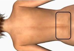
Place the indifferent, dispersive electrode on patient, per figure 3 and connect cable to front of generator (Figure 2, number 2). Ensure entire area of electrode is reliably attached to the patient’s body.
Figure 3. Placement of Indifferent, Dispersive Electrode |
|
|
Place generator footswitch near the surgeon and connect the footswitch cable to front of generator. Refer to Figure 2, number 3.
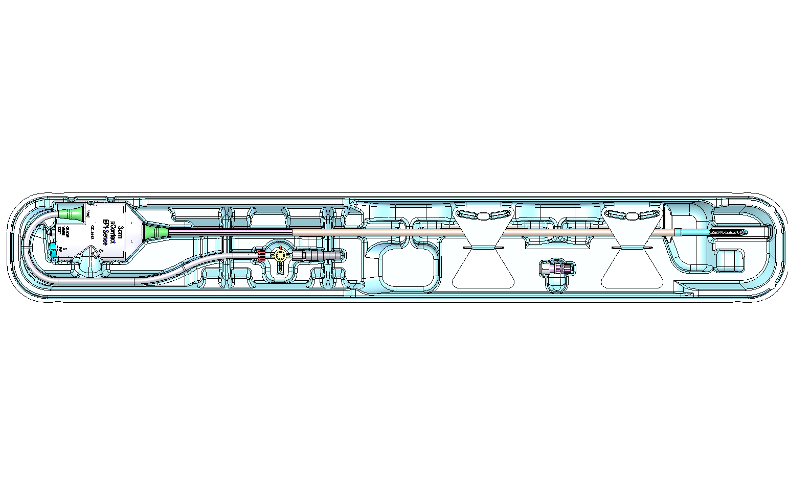
Fig. 4. Coagulation Device in Tray |
|
|
(1) Handle; (2) Stopcock; (3) Tabs; (4) Distal End |


Inspect all trays, pouches, cartons and packaging to ensure there has been no package damage, which may result in product contamination. If package damage is discovered, do not use – replace the product.
Outside the sterile field, remove the tray with the device from the carton.
Inside the sterile field, remove device from the tray (Figure 4) in the following order:
Remove the device from the tray by releasing the tabs (3)
|
|
Prepare the Vacuum
Referring to Figure 5, attach one end of the sterile vacuum tubing to the graduated fitting where indicated on device handle by the vacuum symbol (‘VAC’) and the other to the vacuum trap. Use the stopcock to apply and release the vacuum to the distal assembly.
If graduated fitting is not attached or falls from sterile field, use the extra graduated fitting and attach it to the stopcock (Figure 4, number 4).
Ensure the vacuum unit pressure can reach -400 mmHg.
|
|
Prepare the 0.9% Normal Saline Bag
Place unpressurized saline IV bag at patient height or above.
Connect perfusion tubing to female Luer connection where indicated on device handle by the perfusion “droplet” symbol, (Figure 5, number 1). Verify IV line is fully open.
Insert IV tubing set into 0.9% normal saline bag.
Turn on vacuum pressure and prime device by engaging the suction with a sterile surface (gloved hand).
Ensure
perfusion flow is functioning by observing drops in IV tubing.
Make sure the device is primed by observing perfusion at distal
end of coagulation device before starting operation of device.
Ensure IV line is fully open.


Figure 5. Coagulation Device Key Features |
|
|
|
(1) Perfusion Port, (2) To Saline Bag, (3) RF Cable, (4) Unused port, (5) Stopcock, (6) To Vacuum Tube
|


|
|
Connect nContact RF cable (CS-2000 – provided separately) to device handle where indicated on device handle by ‘RF’ symbol - blue connection to blue connection, (Figure 5, number 3).
![]() CAUTION:
Ensure
arrows on cable and handle are aligned and cable is completely
connected. Device will not register on generator if cable is
incorrectly connected.
CAUTION:
Ensure
arrows on cable and handle are aligned and cable is completely
connected. Device will not register on generator if cable is
incorrectly connected.
Connect the black end of the RF cable to the black Bessel receptacle of the generator front panel connector (Figure 2, number 1).
Figure 6. Generator Back Panel Key Features |
|
|

Connect power cable to generator back panel connector (Figure 6, number 2) then power on the generator via the Power ON/OFF rocker switch (Figure 6, number 1). Refer to the Operator Manual for complete generator instructions.
Place the electrode portion of the coagulation device on desired lesion location using the tether (Figure 1, number 12) to assist in placement. The tether may be cut if required.
Use locator arrows on the device as an aid for the location of the ends of the coil, (Figure 1, number 16).
Hold device on desired location using light pressure until vacuum is engaged.
|
|
Tissue Coagulation
Ensure all steps of device set-up are performed.
Select mode of operation on the generator.
Place device in desired location, using tether if desired. Engage vacuum by turning the stopcock.
Check to make sure perfusion flow is visible, approximately 1 drop per second.
Initiate power by pressing and releasing the footswitch or RF ON/OFF button on generator front panel. An audible signal will sound at the beginning of the RF cycle.
Coagulate tissue for pre-determined cycle.
|
|
|
|
Average Lesion Dimensions |
|||
|
Device Code and Size |
Power Watts |
Time sec |
Depth mm |
Length mm |
Width mm |
Volume mm3 |
|
CS-1201, 1cm |
10* |
120* |
7 |
18 |
10 |
803 |
|
CS-1202, 2cm |
25* |
60* |
6 |
28 |
9 |
1085 |
|
CS-1203, 3cm |
30* |
90* |
7 |
35 |
10 |
1691 |
|
CS-1205, 5cm |
50* |
90* |
7 |
54 |
10 |
2679 |
|
55 |
60 |
7 |
54 |
10 |
2307 |
|
|
60 |
60 |
7 |
53 |
10 |
2326 |
|
*Automatic cycles have been pre-determined for optimal tissue coagulation
When the generator completes a cycle, RF energy turns off automatically, and an audible completion beep sounds for 1 second.
After the cycle is complete, disengage vacuum from the distal end of the device by turning the stopcock lever.
Remove the distal end of coagulation device from tissue and observe completeness of lesion.
Place device electrode in next desired location using tether if desired.
Repeat steps 3-10 from above as needed until desired lesions have been completed
|
|
At completion of procedure, remove device from tissue, disconnect all cables and tubes and discard device, tubing sets and cable following local governing ordinances and recycling plans for disposal or recycling of device components.
Maintenance and Troubleshooting
(see also LBL-1095 nContact Coagulation System Radiofrequency (RF) Generator Unit Model CS-3000 Operators Manual for complete system maintenance and trouble shooting.)
|
Troubleshooting |
|
|
Situation |
Action(s) |
|
Device is not receiving perfusion flow
|
Check perfusion connections on device handle Check perfusion line connection at IV saline bag Ensure perfusion line is fully open Ensure saline bag is not empty Ensure device perfusion line/IV tubing is not clamped/obstructed/kinked |
|
Device is connected but does not register pre-set power and time |
Check all connections to the generator Check the connection of the patient return electrode to the patient Check the cable connection at the handle of the device, the arrows on the cable should be aligned with the arrow on the handle. If both arrows are not aligned, disconnect cable and rotate blue end 180° until aligned then reconnect. |
|
Device does not engage with tissue |
Check vacuum connections on device handle Ensure stopcock lever is in correct position Check vacuum line connection at trap and vacuum unit and ensure other lines are not open Check vacuum pressure – should be approximately –400 to –550 mmHg Ensure that device vacuum line is not clamped/obstructed/kinked Ensure vacuum unit vacuum line is not clamped/obstructed/kinked Check that perfusion set-up is per IFU (i.e. not a pressurized IV system) Ensure that device distal end is shaped to conform to tissue |
|
Generator shuts down during cycle due to high impedance (High impedance warning will be indicated on Generator) |
Check that device is still engaged with tissue (see above if not) Check for excessive material on device electrode, remove material as required Check all cable connections, including indifferent electrode connection Re-start coagulation |
|
Generator does not activate cycle (High impedance warning will be indicated on Generator as “OC” which means Open Circuit) |
Ensure generator is plugged in and turned on Check all cable connections; check indifferent electrode connection for correct position and it is adhered to the patient Ensure device electrode is in direct contact with desired tissue location Check for material on device electrode, remove material as required Check footswitch connection Ensure that generator is in “Power Control Mode” Ensure that Time is not set to “zero” Refer to generator Operator Manual LBL-1095 |
Glossary of Terms
Electro coagulation |
Surgical procedures in which high-frequency electric current is used to coagulate tissues. |
|
Coagulation Electrode |
The metal conductor in the coagulation device used to transmit radiofrequency energy to tissue. |
|
Indifferent, Dispersive Electrode |
Commonly referred to as the “return electrode” or “patient electrode” or “ground pad.” Large surface area indifferent ground used to complete the circuit of the electrical current. Usually placed on the patient’s back or thigh, the indifferent, dispersive electrode is connected to the generator at the Indifferent Connector. |
Abbreviations
RF |
Radiofrequency |
IFU |
Instructions for Use |
|
VAC |
Vacuum |
LBL |
Label |
Symbols
|
|
Manufacturer |
|
Catalog Number |
|
VAC |
Vacuum |
RF |
Radiofrequency |
|
OC |
Open Circuit |
|
Perfusion |
|
|
Equipotential |
|
Defibrillation Proof Type CF Applied Part |
|
|
Indifferent, Dispersive Electrode |
|
Attention, Consult Accompanying Documents |
|
|
Caution: Electrical Shock Hazard |
|
Footswitch Connection |
|
W |
Watts |
Ω |
Ohms |
|
|
Time |
s |
Seconds |
|
|
Authorized Representative |
|
Non-ionizing Radiation |
|
|
Lot Number |
|
Sterile by gamma irradiation |
|
|
Use by |
|
Single Use Only |
|
|
Latex Free |
|
CE Mark and Identification number of Notified body |
|
|
Caution: U.S. Federal law restricts this device to sale by or on the order of a physician or other licensed practitioner. |
|
See instructions for use |
|
|
|
AtriCure Incorporated 7555 Innovation Way Mason, Ohio 45040 USA Customer Service: 1-866-349-2342 (toll free) 1-513-755-4100 (phone) |
Customer Service
LIMITED WARRANTY
AtriCure warrants that reasonable care has been used in the design and manufacture of this instrument. This warranty is in lieu of and excludes all other warranties not expressly set forth herein, whether expressed or implied by operation of law or otherwise, including, but not limited to, any implied warranties of merchantability or fitness for a particular use. Handling, storage, cleaning and sterilization of this instrument as well as other factors relating to the patient, diagnosis, treatment, surgical procedures, and other matters beyond AtriCure control directly affect the instrument and the result obtained from its use. AtriCure’s obligation under this warranty is limited to the repair or replacement of this instrument and AtriCure shall not be liable for any incidental or consequential loss, damage, or expense directly or indirectly arising from the use of this instrument. AtriCure neither assumes, nor authorizes any other person to assume for it, any other or additional liability or responsibility in connection with this instrument. AtriCure assumes no liability with respect to instruments reused, reprocessed or re-sterilized and makes no warranties expressed or implied, including but not limited to merchantability or fitness for intended use, with respect to such instrument.
|
|
|
Page
|
Tags: coagulation system, the coagulation, tethered, system, numeris®, visitrax®, coagulation
- CONVIVIAL DENTAL PC 1244 BOYLSTON STREET CHESTNUT HILL MA
- PHÒNG GD&ĐT BẢO YÊN TRƯỜNG TH SỐ 2 TT
- ANEXO A SOLICITUD DE CONCESIÓN DEL CERTIFICADO DE EMPRESA
- LAB CAMPO ELÉCTRICO Y POTENCIAL ELÉCTRICO LINK SIMULACIÒN HTTPSPHETCOLORADOEDUSIMSHTMLCHARGESANDFIELDSLATESTCHARGESANDFIELDSESHTML
- VÝVOJ APLIKACÍ XML S VYUŽITÍM PROGRAMOVACÍHO JAZYKA JAVA BAKALÁŘSKÁ
- “AND SO MY FELLOW AMERICANS ASK NOT WHAT YOUR
- 12 PERATURAN PEMERINTAH REPUBLIK INDONESIA NOMOR 46 TAHUN 2008
- ANALISIS RAZONADO DEL BALANCE GENERAL EMPRESAS IANSA SA AL
- AVSTANDSERKLÆRING ( VEDLEGG TIL SØKNADMELDING ) VEDRØRENDE EIENDOMMEN GNR
- MURRAY—DARLING BASIN AUTHORITY MURRAY COD MODELLING TO ADDRESS KEY
- LISTA JEDNOSTEK NIEODPŁATNEGO PORADNICTWA DOSTĘPNEGO DLA MIESZKAŃCÓW KIELC TEMATYKA
- TESORERÍA FECHA RECEPCIÓN PLAZA DE LA CONSTITUCIÓN 2
- RDEČI KRIŽ SLOVENIJE PRVA POMOČ 112 VPRAŠANJ IZ PRVE
- 14 CONSTRUÇÃO DE CONCEITOS MATEMÁTICOA NO ENSINO TÉCNICO PARA
- FORMULAR ZUR SELBSTBEWERTUNG THÉÂTREPROVS EINES ABGESCHLOSSENEN STAAT WALLIS
- AFFIDAVIT FOR INTERCASTE MARRIAGE BEFORE REGISTRAR AFFIDAVIT I
- SR DIRECTOR ADJUNTO REMITIMOS UN TRABAJO QUE DESEARÍAMOS FUESE
- UNIDAD 3 WHERE ARE YOU FROM? TEMAS 1NACIONALIDADES Y
- ÁREA DE PROCESOS LEGISLATIVOS 30 EXP Nº
- CHP RFO FAQS DATE 2232012 MY FACILITY DOES NOT
- JOB TITLE REGIONAL VOLUNTEER COORDINATOR TEAM RESETTLEMENT TEAM
- 31 TITLE EMPATHICLIKE RESPONDING BY DOMESTIC DOGS (CANIS FAMILIARIS)
- CONTRATO DE COMISIÓN MERCANTIL QUE CELEBRAN POR UNA PARTE
- MERKEZ BİRLİK TÜZÜK YUMURTA ÜRETİCİLERİ MERKEZ BİRLİĞİ TÜZÜĞÜ BİRİNCİ
- CEREBROSPINAL FLUID (CSF) CELL COUNT AND DIFFERENTIAL CYTOCENTRIFUGE TECHNIQUE
- APPLICATION FORM POSITION APPLIED FOR 1 PERSONAL
- HRVATSKA KOMORA FIZIOTERAPEUTA NA TEMELJU STATUTA HRVATSKE KOMORE FIZIOTERAPEUTA
- NOTICE OF APPEAL UNDER SECTION 7 OF FISHERIES (AMENDMENT)
- VICERRECTORIA DE INVESTIGACION Y DESARROLLO BARRIO UNIVERSITARIO SN •
- LANZAMIENTO REGIONAL DE LA SVA HAITI FECHA
 X VI OGÓLNOPOLSKI KONKURS ONLINE „ULUBIONE PIEŚNI JANA PAWŁA
 GOLD STANDARD MICROPROGRAMME OF ACTIVITIES DESIGN DOCUMENT FORM (POADD)
 1 RECHERCHER L’INFORMATION NÉCESSAIRE À LA RÉALISATION DE LA
DISPOSITION OF REMAINS REPORT MOZAMBIQUE UPDATED AUGUST 2017 (1)
2 A) MELLÉKLET A 2102009 (IX 29) KORM RENDELETHEZ
 THE 18TH JAPAN STUDY ABROAD PROGRAM ECON 330V SUMMER
 RECORDS MANAGEMENT POLICY MINSTER MEDICAL GROUP MINSTER MEDICAL CENTRE
 REGISTRO DE APROBACIONES Y COMUNICACIONES DE ESPECIFICACIONES PARTICULARES SOBRE
 W WWPFIZERES CADA DÍA ENTRE TRES Y CUATRO PERSONAS
28 ULUSLARARASI İSTANBUL FİLM FESTİVALİ’NDE SÜRPRİZ FİLMLER EK SEANSLAR
 TÉCNICAS DE INDUMENTARIA II UNIDAD N1 ESTRUCTURA OPERATIVA DE
PATVIRTINTA 2014 M BIRŽELIO 13 D BENDRIJOS PIRMININKĖS ĮSAKYMU
MJERA 1 MJERA 2 IZJAVA O BROJU
KAS MES ESAME 2016–2017 M M SIEKĖME DEMOKRATIŠKESNIŲ TARPUSAVIO
EURÓPAI ALKOTMÁNY ÉS JOGTÖRTÉNET – DR ANTAL TAMÁS
 KARTA USŁUGI NR OK 13 ZASIŁEK SZLOLNY (
 GHANI KHAN CHOUDHURY INSTITUTE OF ENGINEERING & TECHNOLOGY (UNDER
VOCABULARY ENRICHER (NONFICTION) NAME GROUP BOOK ASSIGNMENT P
JOGA NI NEDOLŽNA ŠALA (RESI NAS HUDEGA AMEN) NEW
 MOD09CMG005 DATA DOWNLOAD REPORT AUGUST 10TH 2009 DESCRIPTION THE
