A WARPBASED FEATURE TRACKER THOMAS KANG1 JIM GEMMELL2
A WARPBASED FEATURE TRACKER THOMAS KANG1 JIM GEMMELL2
Warp Tracking
A Warp-Based Feature Tracker
|
Thomas Kang1 |
Jim Gemmell2 |
Kentaro Toyama3 |
October 29, 1999
Technical Report
MSR-TR-99-80
Microsoft Research
Microsoft Corporation
One Microsoft Way
Redmond, WA 98052
Abstract
We present the warp tracker, a new system for tracking features through a sequence of images. Employing an automated multi-resolution lattice deformation technique, the warp tracker performs fairly well on its own, and its hierarchical nature naturally lends itself to being integrated with other tracking algorithms for increased accuracy and robustness. Developed specifically for use in next-generation video teleconferencing systems, a prototype of the warp tracker has already been tested on tracking human eyes with encouraging results.
Introduction
Feature tracking involves locating a set of features – e.g., points, lines, objects – through a sequence of images as those features move around and alter their pose. This paper describes a new feature tracking algorithm, which we call warp tracking, designed to work as a part of a video conferencing system, in which the eyes of participants must be tracked and replaced with synthetically rendered eyes to correct gaze direction in real time [Zit99].
Existing feature trackers can be classified roughly into two categories: contour trackers and region trackers. Contour trackers attempt to follow the precise outline of a feature in images. Snakes, first proposed by Kass et al. [Kas88], are particularly popular for this purpose. Snakes use variational techniques to solve an energy minimization formulation of the tracking problem. The chief advantage of snakes is that they are able to track arbitrarily shaped features. However, due to their dynamic nature, they tend to be numerically unstable, hard to manipulate, and susceptible to being thrown off by noise.
In contrast, region trackers return the portions of the images that contain the feature but do not necessarily form a tight bound, sacrificing preciseness in exchange for increased robustness. A good recent example of region tracking is [Hag98].
In essence, the difference between contour and region tracking is that of local versus global analysis. Contour trackers rely on local analyses of the images in the vicinity of the feature, whereas region trackers analyze entire images for more globally optimal solutions. This explains the preciseness-versus-robustness tradeoff described above: local analysis leads to locally optimal solutions that may not be globally optimal, which leads to instability; and global analysis must rely on some sort of a region-based scheme to make it run at a reasonable speed, which leads to reduced precision. Of course, there are many trackers that lie somewhere between these two extremes; however, to date there have been no trackers that explicitly merge the two into a hybrid approach.
The warp tracker was developed to bridge the gap between contour tracking and region tracking by spanning the space between local and global analyses using a coarse-to-fine technique. The particular coarse-to-fine algorithm we employ for the warp tracker is based on the results of Gao and Sederberg [Gao98], which uses a set of bilinear B-spline grids to gradually tighten the boundaries of control from the global to the local. This leads to a system that merges the preciseness of contour tracking with the robustness of region tracking, though it does sacrifice a little with respect to both. However, this system could then easily be placed between a region tracker and a contour tracker in a tracking pipeline.
Section 2 discusses the warp tracker in detail and offers an analysis of its strengths and weaknesses. Section 3 presents the test results of the prototype warp tracker that was developed. Section 4 describes some future work, including the tracking pipeline proposed above. Section 5 concludes the paper.
Warp Tracker
The
warp tracker is initialized with an initial (e.g., canonical) image
and contour, which we call the source. Then, for any subsequent
target image in which we wish to track the contour, we compute the
correspondence map between the source and target images and apply it
to the source contour to yield the target contour. More formally,
let I0 and I1 be the source and
target images, respectively, and let C0 and
C1 be source and target contours,
respectively. Then we compute the map
![]() ,
and finally we compute
,
and finally we compute
![]() .
.
The main difficulty lies in computing M, which is a hard computer vision problem. We follow [Gao98], which is to define a warp function G over I0, which is essentially a deformable multi-resolution grid. The grid can be warped subject to several geometric restrictions (described below), and its deformation causes the underlying image I0 to deform along with it. We then define an energy function E over the grid, which has the property that its value is inversely proportional to the accuracy of the correspondence map defined by G. We can then reformulate the task of computing M as an energy minimization problem, in which we try to find the optimal warp Gopt that minimizes E.
We can break down the warping algorithm into three major parts: the general grid operations, the energy metric defined over the grid, and the energy minimization routine. We examine each of these below.
1Grid Operations
The grid that represents the warp function G is composed of bilinear B-spline patches and can be subdivided ad infinitum to produce finer and finer grids. The ith level grid contains 2i2i patches, and the control points of the grid are the vertices of the grid patches. We chose bilinear B-spline patches largely because they lead to relatively fast implementations of the operations we wish to support, which are described below.
The grid can be warped by moving its control points to different locations, subject to several restrictions (Figure 1). To preserve the convexity of the patches, we stipulate two conditions: first, the ordering of the control points must be maintained in both x and y directions; i.e., points are not allowed to move past neighboring points. This prevents “folding” of the patches. Second, all points must remain within the region defined by the diagonals connecting its neighboring points. For example, given an interior point p, it has neighbors to its immediate north, south, east, and west. By connecting these four neighbor points, we form a diamond-shaped region, outside of which p is not allowed to move. While there is no fundamental reason for imposing these geometric constraints, in practice these constraints greatly speed up computations, and they also seem to model affine transformations well, at least for small displacements.
|
|
|

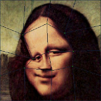
Figure 1: The image on the left is the original image with a level two grid superimposed over it. The image on the right is an example of a warp function applied to the image.
When the grid undergoes subdivision, it simply subdivides each of its patches into four child patches. This requires the creation of five new control points – one at the midpoint of each edge, plus one at the center of the patch. To subdivide a warped patch, we interpolate the midpoint along each of the four edges of the patch to generate four of the new control points. For the final control point at the center of the patch, we compute the intersection of the line connecting the midpoints of the top and bottom edges and line connecting the midpoints of the left and right edges.
Mapping any point (x,y) in I0 to its corresponding point in the warped image G(I0) involves the same computation as polygonal texture mapping, namely bilinear interpolation: first locate the patch P which contains the point and compute the local coordinates (u,v) within that patch. Then locate the corresponding warped patch P’ in G(I0) and linearly interpolate u horizontally and v vertically in P’ to derive (u’,v’). Finally, map (u’,v’) back into the image space to derive (x’,y’) in G(I0).
2Energy Metric
The energy metric E is a scalar function defined over the grid, the value of which is minimized to result in an optimal warp. The metric we use has two components: 1) the color difference between the warped source image and the target image, and 2) the extent of deformation as determined by the amount of deformation experienced by each grid patch edge. We call these the color and geometric terms, respectively. That is:
![]()
The color term in turn depends on a color similarity metric :
![]()
We have experimented with various ways to define , including the Cartesian distance in RGB space and absolute difference of the luminosity. They all yielded similar results, which leads us to believe that any general-purpose metric will suffice. However, it is quite possible that a more sophisticated domain-specific metric might yield better results; e.g., a face-tracking system might benefit from using a metric that more sharply distinguishes flesh tones from non-flesh tones.
The geometric term depends on two types of deformations, linear and angular:
![]()
Here, e are the edges in G and are the angles between any two adjoining edges in G. Thus, the first summation computes the sum of the squares of how much each edge stretched or contracted in the deformation, and the second summation computes the sum of the squares of how much each patch corner bent in the deformation.
In practice, we got the best results by scaling the weighting factors so that the color term clearly dominates. In most cases, we have found that the angular term doesn’t seem to contribute much in most cases, so it is often possible to save some computation time by completely eliminating it without any significant effect on the tracking accuracy.
3Energy Minimization
Let
npix be the number of pixels in the image
and ncp be the number of control points on
the grid. Then there are
![]() possible warps, so in general, searching for Gopt
is an exponential problem, making a brute-force exhaustive search
impossible. Even if we impose a restriction to allow only those
warps that preserve the convexity of all constituent patches,
exhaustive search is still too costly, especially if we want this
system to run at real-time rates.
possible warps, so in general, searching for Gopt
is an exponential problem, making a brute-force exhaustive search
impossible. Even if we impose a restriction to allow only those
warps that preserve the convexity of all constituent patches,
exhaustive search is still too costly, especially if we want this
system to run at real-time rates.
[Gao98] proposes a fast, simple polynomial heuristic that empirically gives good results for their input images. However, in practice it proves to be rather sensitive to the nature of the input images, and it also contains many implementation- and input-dependent constants that must be adjusted for proper behavior. Furthermore, they admit in the paper that their routine often needs additional user input – in the form of anchor points – to help guide the search. This sort of user intervention is impossible to give in real-time scenarios such as ours.
We use an alternate energy minimization routine that is more robust and less reliant on specially selected constants and user intervention. It is a variation on the exhaustive search, but it mitigates the exponential blowup by pruning impossible candidate locations. Figure 2 gives the pseudocode for our algorithm.
for i=1 to imax {
for each control point p Gi {
emin = E(Gi, I0, I1)
Lmin = location (x,y) of p
for each location L in patches containing p in Gi {
if p is allowed to move to L then
move p to L; call this grid Gi’
ecur = E(Gi’, I0, I1)
if ecur < emin then
emin = ecur
Lmin = Lcur
else
move p back to Lmin
end if
end if
next L
next p
next i
Figure 2: The energy minimization routine used in the prototype warp tracker is shown here in pseudocode.
Note that a patch P is said to contain a control point p if p is one of the vertices of P. Thus, all corner points have one containing patch, edge points have two, and interior points have four. Note also that the test to see if p is allowed to move to L involves testing to make sure the resulting warp preserves convexity as noted above. Though this algorithm is theoretically slower than the one described in [Gao98], it runs fairly quickly in practice, especially for smaller images.
Results
We have implemented a prototype warp tracker and tested its speed, accuracy, and robustness with respect to several different data sets. The user interface is shown in Figure 3: the left image pane shows the canonical image with the deformable grid superimposed on it, and the right image pane shows the target image on which to track. The user first draws the desired contour directly on the left image using a mouse, which in this case is a set of white points around Mona Lisa’s left eye. The contour is displayed on the right image as well. The points are automatically connected with a Catmull-Rom spline, drawn in red, which was chosen for its interpolating property. Once the contour has been drawn, the user simply clicks the “Go!” button to activate the warp tracker, which computes the optimal warp of the first image to generate the correspondence map between the two images and then uses the map to warp the contour into place in the target image.
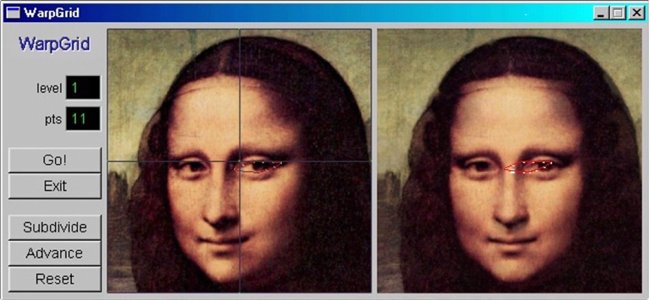
Figure 3: This is a screenshot of the warp tracker. The image on the left is the canonical image; the image on the right is the image on which the contour must be tracked. The initial contour is drawn directly onto the left image, and then the user presses the “Go!” button, at which point the computer takes over and automatically generates the tracked contour in the second image.
On a Pentium II/333 with 256 MB of RAM running Windows 2000 Professional beta 1, we were able to achieve 1.5 frames per second for 32x32 images and fourfold subdivision (i.e., final grid patches covering 2x2 pixels prior to warp). While this is still far from real-time performance, we have a number of ideas for speeding up our current implementation. Also, since the system is primarily processor-bound, upgrading to a faster processor – e.g., the current top-of-the-line Pentium III/600 – should yield noticeably better performance even without any tweaking of the algorithm itself.
Figure 4 illustrates the ability of the warp tracker to handle gross translations and rotations. The different views of Mona Lisa were generated via view morphing [Sei96]. To highlight the ability of the warp tracker to track features through significant morphological changes, we also generated a 208 image sequence of a blinking eye. The results for those images are shown in Figure 6.
|
|
|
|
|
|
|
|


Figure 4: This data set is designed to test the warp tracker’s ability to track gross motions – in this case, upper body rotation. The upper left image is the canonical image, for which the contour was manually initialized by the user. The contours in the rest of the images were then automatically generated by the warp tracker with no further user input.
Future Work
Our prototype system has yielded encouraging results, but there is still plenty of room for improvements on all fronts. Below, we discuss ways to gain greater accuracy and performance from the warp tracker, including a major architectural change involving a pipeline of three separate tracking algorithms working in tandem.
4Warp Tracker Improvements
Perhaps the most obvious improvement one can make on the warp tracker would be to modify the energy minimization routine. As long as the energy metric is relatively smooth and differentiable, which is the case for the metric presented above, we can minimize it using a more sophisticated nonlinear optimization algorithm for a significant gain in speed. However, it is unclear at this point whether this approach may also adversely affect the accuracy of the algorithm. Essentially, the smoothness of the metric with respect to the deformation will determine the effectiveness of these gradient-based minimization routines.
Along those lines, the energy metric itself could also be improved upon. For example, there is currently no explicit bias in the metric for affine transformations. Furthermore, if a gradient-based minimization routine is used as described above, it may be possible to reformulate the energy metric so as to improve its behavior with respect to the routine.
5Tracking Pipeline
One significant shortcoming of the warp tracker is that it inherits not only the strengths of the region and contour trackers, but their weaknesses as well. For example, the robustness of the warp tracker is somewhat diluted compared to that of a region tracker, so it cannot handle large displacements very well. Intuitively, a large displacement induces a severe warp of the grid, which in turn cause the geometric term in the energy metric to dominate and thus resist warping to the extent required to correctly track the feature. Similarly, the preciseness of the warp tracker is also somewhat compromised: the contour returned by the warp tracker is sometimes off by a few pixels, depending on the final level of grid subdivision. Essentially, to guarantee pixel-level accuracy of the contour, the grid must ultimately be subdivided to individual pixels.
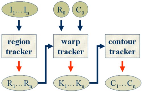
Figure 5: This is the schematic of the complete tracking pipeline. I1…In are input images; R0 is the region containing the feature in the initial image; C0 is the contour of the feature in the initial image; R1…Rn are feature regions; K1…Kn are approximate contours; and C1…Cn are final contours.
Unfortunately, one cannot remedy these problems directly within the warp tracker. Subdividing the grid down to individual pixels, for example, would cause the warp tracker to take an unacceptably long time to run. Instead, we propose a more sweeping solution to these problems, where the warp tracker is augmented with both a region tracker and a contour tracker in a pipeline (Figure 5).
Our modified feature tracker consists of the three tracking algorithms arranged as stages in a tracking pipeline. As before, the system is first initialized with an initial image and contour, so that the system knows what to track. Then the subsequent stream of images are processed sequentially by these three algorithms in the order presented above, with the output of each stage serving as the input to the next stage. In other words, each stage refines the tracking result of the previous stage.
This arrangement allows all three algorithms to exercise their strengths while compensating for each other’s weaknesses. Specifically, the region tracker can robustly track even large displacements to yield regions with much smaller apparent displacements, which the warp tracker can then handle to generate an approximate contour that the contour tracker refines into a tight contour.
There are many region and contour trackers from which to choose. However, while it is imperative that the region tracker be as robust as possible, the contour tracker can be fairly simple. This is because in our system, both the region tracker and the warp tracker precede the contour tracker, so we can assume that the input to the contour tracker always will be fairly close to the actual contour. Thus, even a simple local gradient-driven tracker should be enough to give fairly good results. However, the imposition of some rudimentary (i.e., not necessarily domain-specific) geometric constraints may still be helpful – e.g., enforcing the relative ordering of the feature points along the contour.
We found that our prototype implementation benefited significantly from the addition of a region tracker; however, we have not yet implemented a contour tracker. That the output from this two-stage pipeline system are consistently within just a few pixels of the actual contour corroborates the above analysis and leads us to believe that the addition of a contour tracker will further improve the performance of the system. We plan to implement a contour tracker in the next phase of this project.
Conclusions
We have presented the warp tracker, a new feature tracking algorithm that employs an automated multi-resolution lattice deformation technique to combine the robustness of a region tracker with the preciseness of a contour tracker, and demonstrated its efficacy in general-purpose feature tracking. We have also described a tracking pipeline, in which the warp tracker serves as a bridge between region and contour trackers, an arrangement which greatly increases the robustness and decreases the overall complexity of the system. Its ability to track features through changes in shape as well as location makes the warp tracker especially promising for applications such as video conferencing.
Acknowledgements
This work is the result of a summer internship at the Microsoft Bay Area Research Center. We would like to thank Steve Seitz and Jim Gray for their insightful comments and critiques through all phases of this project.
References
|
[Bei92] |
T. Beier and S. Neely. “Feature-based image metamorphosis,” Proc. SIGGRAPH 92. In Computer Graphics (1992), pp. 35-42.
|
|
[Gao98] |
P. Gao and T. Sederberg. “A work minimization approach to image morphing.” In The Visual Computer (1998), pp. 390-400, Springer-Verlag.
|
|
[Hag98] |
Hager, G.D. and Belhumeur, P.N., “Efficient Region Tracking with Parametric Models of Geometry and Illumination”, PAMI, Vol. 20, No. 10, Oct. 1998, pp. 1025-1039.
|
|
[Kas88] |
M. Kass, A. Witkin, and D. Terzopolous. “Snakes: Active Contour Models,” International Journal of Computer Vision (1988), pp. 321-333.
|
|
[Sei96] |
S. Seitz, C. Dyer. “View Morphing,” Proc. SIGGRAPH 96. In Computer Graphics (1996), pp. 21-30.
|
|
[Zit99] |
C. Lawrence Zitnick, J. Gemmell, and K. Toyama. “Manipulation of Video Eye Gaze and Head Orientation for Video Teleconferencing,” Technical Report MSR-TR-99-46. Microsoft Research, Redmond, WA. June, 1999. |
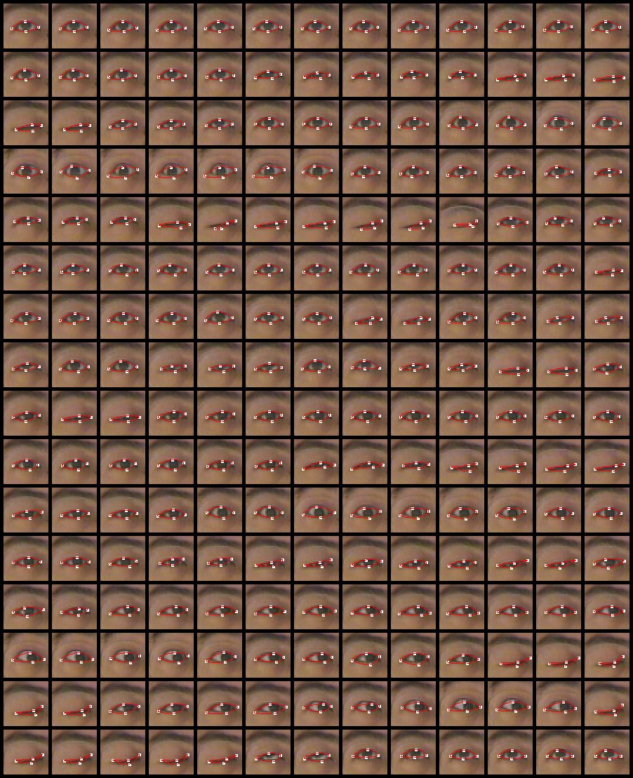
Figure 6: This data set tests the warp tracker’s ability to track changes in shape. The upper left image is the canonical image, for which the contour was manually initialized by the user. The contours in the rest of the images were then automatically generated with no further user input.
Tags: feature tracker, general-purpose feature, tracker, feature, kang1, gemmell2, warpbased, thomas
- ŞARKÖY BELEDİYE BAŞKANLIĞI MAYIS 2019 MECLİS KARAR ÖZETLERİ KARAR
- ANSØGNINGSSKEMA FOR OPTAGELSE I EURESNETVÆRKET SOM MEDLEM ELLER PARTNER
- MARCH 28 2002 COMPARING PALESTINIAN AND ISRAELI TEXTBOOKS BY
- MINIMUM REQUIRED RESIDENTIAL INSPECTIONS BY PROJECT THE FOLLOWING MINIMUM
- ZO162021 SPECYFIKACJA ISTOTNYCH WARUNKÓW ZAMÓWIENIA ŚWIADCZENIE USŁUG W ZAKRESIE
- 1 SOFT CRAFT HARD CHOICES ALTERED CONTEXT REFLECTIONS ON
- AR ACCOUNTS RECEIVABLE MENU AR ACCOUNTS RECEIVABLE
- EQUESTRIAN AUSTRALIA TD CHECK LIST AND REPORT NAME OF
- KATALOG INFORMACIJA 1 UVODNE ODREDBE KATALOG INFORMACIJA SADRŽI PREGLED
- STATE OF NEW YORK TOWN OF CORTLANDT PLANNING BOARD
- PRESS CLIPPING FMAT 2015 WFAL 2015 (OCTOBER 2014JULY 2015)
- ESPACIO RESERVADO PARA EL REGISTRO DIRECCIÓN GENERAL DE INDUSTRIA
- TRIATLOI EPAILE AUTONOMIKOA (1 MAILAKO OFIZIALA) IZATEKO IKASTAROA ETA
- SIERRA DE ALCARAZ CIRCULAR INFORMATIVA 01 06 ÓRGANO
- THE FRIENDSHIP FUND EASTSIDE MARKETPLACE IS PLEASED TO OFFER
- MATEMÁTICAS I Y II INTRODUCCIÓN LAS MATEMÁTICAS CONSTITUYEN UNA
- MODELO DE CASO SERVICIO DE INDICACIÓN FARMACÉUTICA COLEGIO OFICIAL
- ASSERTIVENESS W9 STUDENT COUNSELLING CAREER AND DEVELOPMENT CENTRE SUMMERSTRAND
- ROZLICZENIE DOFINANSOWANIA ZE ŚRODKÓW NA DZIAŁALNOŚĆ DOKTORANCKĄ KOD DOFINANSOWANIA
- DOCUMENTO DE ORIENTACIÓN LA BIOMASA EN EL RCDE UE
- DETAIL SHEET INSTRUCTIONS THE DIVISIONS WILL HAVE APPROXIMATELY 10
- UNIVERSITAS SARJANAWIYATA TAMANSISWA FAKULTAS KEGURUAN DAN ILMU PENDIDIKAN
- LICENSING ACT 2003 GUIDANCE NOTE – MAKING A REPRESENTATION
- WHEN I WAS NINE YEARS OLD I WENT OFF
- BANDO LIFE 20052006 — INVITO A PRESENTARE PROPOSTE NELLAMBITO
- CONTACT INFORMATION TIEQIANG LI 10 CENTER DR NINDS NIH
- EVEN START EVEN START IS A FREE FAMILY LITERACY
- PROTECTION AND PERMANENCY TRANSMITTAL LETTER PPTL0904 TO SERVICE REGION
- ASSEMBLY CONCURRENT RESOLUTION NO 210 STATE OF NEW JERSEY
- LIGHT SPORT AVIATORS’ MODEL CODE OF CONDUCT RECOMMENDED VOLUNTARY
 REPUBLICA ORIENTAL DEL URUGUAY ADMINISTRACIÓN DE LAS OBRAS SANITARIAS
UPPLANDSBRO KOMMUN DATUM VÅR BETECKNING 2 (2) 20191218 TN
 NEDĒĻAS EKSPERTI RVANAGA NVAN GEJEKA P25 BLOKS PIEKTĀS NEDĒĻAS
 GÖĞÜS HASTALIKLARI YETERLİLİK SINAVI BAŞVURU FORMU (SINAVA KATILMAK ISTEYEN
 DFM16 GLUKOSMETABOLISMEN ANNELIE PETTERSSON SAMMANFATTNING GLUKOSMETABOLISM HORMONELL REGLERING
 YABANCI BİLİM ADAMI VE MEŞHURLARIN KUR’ÂN’I KERÎM (İSLÂM) HAKKINDAKİ
 AYUNTAMIENTO DE ORIHUELA ACTA 52018 ASISTENTES SR ALCALDEPRESIDENTE D
 PRIMER PREMIO NACIONAL DE TEXTO DRAMÁTICO “DULCE POR AMARGO”
FINANCING AGREEMENT SPECIAL CONDITIONS THE EUROPEAN COMMISSION HEREINAFTER REFERRED
BROJ 129 196221 DATUM 21062021 GODINE S V I
NOTA DE PRENSA IKEA RETIRA EL SACO DE DORMIR
 DNIA (MIEJSCOWOŚĆ) WNIOSEK O SPRAWDZENIE I PRZYŁĄCZENIE INSTALACJI
 POWERPLUSWATERMARKOBJECT87102676 UNIWERSYTET WROCŁAWSKI INSTYTUT FILOLOGII ROMAŃSKIEJ KIERUNEK FILOLOGIA SPECJALNOŚĆ
 PAYMENT FORM (REVISED 0616) DATE OF RECEIPT (FOR OFFICE
PROVEDBA DDD MJERA KAO POSEBNIH MJERA ZAŠTITE PUČANSTVA OD
2 PROGRAM ZEBRANIA 1 ROZPOCZĘCIE ZEBRANIA 2 WYBÓR PROTOKOLANTA
 LICITACIÓN ABREVIADA N° 2010000093PROV “ADQUISICIÓN E INSTALACIÓN DE SISTEMA
 s Upporting Documentation – Standard Cover Sheet Supporting Documentation
DISCOURS DU MINISTRE DES AFFAIRES ÉTRANGÈRES MONSIEUR HIROFUMI NAKASONE
 5 DAS BEWERBUNGSGESPRÄCH1 EIN BEWERBUNGSGESPRÄCH IST EINE GESPRÄCHSSITUATION
