SWELLING OF GLASSFIBER REINFORCED POLYAMIDE 66 DURING CONDITIONING IN
14 SWELLING AND OPTICAL PROPERTIES OF SI3N4 FILMS IRRADIATEDA RECURRENT LIPS SWELLING QUIZ SETTINGS PROPERTY SETTING
REOLOGI SIFAT AGING TERMAL DAN SWELLING DARI CAMPURAN EPDMNR
SWELLING OF GLASSFIBER REINFORCED POLYAMIDE 66 DURING CONDITIONING IN
Dependence of interfacial strength on the anisotropic fiber properties of jute reinforced composites
Swelling of glass-fiber reinforced Polyamide 66 during conditioning in water, ethylene glycol and antifreeze mixture.
J. L. Thomason and G.Porteus
University of Strathclyde, Department of Mechanical Engineering, 75 Montrose Street, Glasgow G1 1XJ, United Kingdom.
Swelling of glass-fiber reinforced Polyamide 66 during conditioning in water, ethylene glycol and antifreeze mixture.
J. L. Thomason and G.Porteus
University of Strathclyde, Department of Mechanical Engineering, 75 Montrose Street, Glasgow G1 1XJ, United Kingdom.
Abstract
The weight and dimensional changes of injection molded glass-fiber reinforced polyamide 66 composites based on two glass fiber products with different sizing formulations and unreinforced polymer samples have been characterised during conditioning in water, ethylene glycol and a water-glycol mixture at 50°C and 70°C for a range of times up to 900 hours. The results reveal that hydrothermal ageing in these fluids causes significant changes in the weight and dimensions of these materials. All conditioned materials showed a time dependent weight and dimension increase. The change observed in water could be well modelled by a simple Fickian diffusion process, however the absorption process followed a more complex pattern in the other conditioning fluids. It was not apparent that changing the glass fiber sizing affected the dimensional stability of the composites under these relatively mild conditions. There was a strong correlation between the swelling of these samples and the level of fluid absorption. The composites exhibited highly anisotropic levels of swelling. These effects were well in line with the influence of fibers on restriction of the matrix deformation in the fiber direction. The polymer and composite swelling coefficients correlated well with data previously obtained at higher conditioning temperatures.
Introduction
Glass fiber reinforced polyamides, such as polyamide 6 and 66, are excellent composite materials in terms of their high levels of mechanical performance and temperature resistance. However, the mechanical properties of polyamide based composites decrease markedly upon absorption of water and other polar fluids. The mechanical performance of these composites in a hydrothermal environment results from a combination of the fiber and matrix properties and the ability to transfer stresses across the fiber-matrix interface. Variables such as the fiber content, diameter, orientation and the interfacial strength are of prime importance to the final balance of properties exhibited by injection molded thermoplastic composites [1-5]. Short fiber reinforced thermoplastics have been used in the automotive industry for many years and there has recently been a strong growth in the use of polyamide based materials in under-the-hood applications [6]. These applications place stringent requirements on such materials in terms of dimensional stability and mechanical, temperature and chemical resistance. There has been a rapid increase in the number of molded composites exposed to engine coolant at high temperatures [7-10] and this has led to a need for an improvement in our understanding of the performance of glass-reinforced-polyamide under such conditions.
Typical testing for these applications involves measurement of mechanical properties before and after conditioning of the test material in model (water – ethylene glycol) coolant fluids for a fixed time, up to 1000 hours, at temperatures in the 100-150°C range. It is not always easy to obtain a good understanding of the structure-performance relationships of a material from such snapshots of performance taken at a single condition. However, it has been known for sometime within the industry that the chemical nature of the glass fiber sizing can have a strong influence on the retention of some mechanical properties of composites exposed to such hydrothermal conditioning. It is also well known that polyamide materials absorb relatively high levels of moisture when exposed to hydrothermal conditioning in water and that this can cause significant dimensional changes [11-17]. Despite this, and the fact that such hydrothermal testing has become commonplace for under-the-hood applications, there has been little systematic investigation of dimensional change of glass-fiber reinforced polyamide composites during such conditioning in coolant fluid. Thomason [17] has recently reviewed the mechanical performance and dimensional changes observed in glass fiber reinforced polyamide 66 during conditioning in coolant fluid at 120°C and 150°C. A rapid reduction was observed in both the modulus and strength of these composites and the matrix polymer in the initial stage of conditioning. However, unnotched impact was seen to initially increase significantly. Due to the rapid rate of fluid absorption and dimensional change at these high temperatures it was not possible to examine these effects in detail. Thomason and Ali investigated the mechanical performance and weight and dimensional changes in similar materials at the lower temperature of 70°C [18]. They reported a pseudo-Fickian absorption process in their GF-PA66 samples and a highly anisotropoic swelling in their injection molded composites which could be correlated with the fiber orientation. In another recent paper [19] the same authors confirmed the presence of an increase in unnotched impact performance during the early stages of conditioning and indicated that there is a possibility to superimpose results of mechanical testing GF-PA66 samples conditioned in coolant at different times and temperatures by considering the level of swelling and fluid absorption in any individual sample.
There is as yet little information available clarifying whether the two main components of such water-glycol mixtures have an equally deleterious effect on the dimensional stability and mechanical performance of glass-fiber reinforced polyamides. In an attempt to gain further insight into these effects this report presents the results of a further systematic study of the changes of dimension of injection molded glass reinforced polyamide 66 composites during hydrothermal conditioning in model coolant fluid and its two main components. The weight and dimensional changes and mechanical properties of injection molded glass-fiber reinforced polyamide 66 composites based on two glass fiber products with different sizing formulations and unreinforced polymer samples have been characterised during conditioning in water, ethylene glycol and a water-glycol mixture at 50°C and 70°C for a range of times up to 900 hours. This report focuses on the results of the swelling measurements. Detailed discussion on the absorption processes and thermo-mechanical property changes of these materials will be presented elsewhere [20].
Experimental
The injection molded polymer and composite bars for this study were supplied by the 3B fiberglass company. The polyamide 66 (PA66) used was DuPont Zytel 101. Composite samples with 29% weight fiber content were produced using this polymer and two chopped AdvantexTM E-glass products. AdvantexTM is a boron free E-glass formulation. These products were chopped to a length of 4 mm and the individual fibers had a nominal average diameter of 10 m. Both samples were coated with sizings which are designed for polyamide reinforcement. DS1143 is a typical sizing designed to maximise the “dry as molded” (DaM) performance of glass reinforced polyamides. The main ingredients of such sizings are typically aminosilane coupling agent and a commercial polyurethane dispersion [18-22]. DS1110 sizing contains some extra components which enhance the retention of composite mechanical properties in elevated temperature hydrolytic environments [18,19]. Three series of samples were molded, series A using DS1143 glass, series B using DS1110 glass, and series R containing only the PA66 resin. The glass and polymer were compounded on a twin screw extruder and injection molded to produce end-gated rectangular bars of with nominal dimensions 80x10x4 mm.
These test bars were received vacuum packed in a DaM state. On removal from the packaging all samples were weighed and their three dimensions recorded at room temperature prior to conditioning. A micrometer with an operating range between 0-50mm ± 0.005mm was used in order to measure the width and the thickness of the test samples. It is well known that the cross section of injection molded samples may not be exactly rectangular and it was noted that the recorded dimension varied slightly dependent on where the measurement was taken. To ensure consistency measurements were therefore taken at the exact centre of each sample, as per ISO 179. The sample bars length exceeded the range of the micrometer and so the length of the test samples was measured using a vernier calliper with an accuracy of ±0.01 mm was used. A digital balance with an operating range between 0-20 g ± 0.0001 g was used to measure sample weights. Each data point presented is the average of measurements on three individual samples. Hydrolysis conditioning took place in two temperature controlled water baths at 50°C or 70°C with samples fully immersed in one of the three test fluids, deionized water (W), ethylene glycol (EG), or a 50:50 mixture of water and glycol (AF). Samples were stacked vertically and individually in polypropylene seal-tight containers such that the fluid had access to all surfaces of each sample. The water baths and containers of conditioning fluid were allowed to equilibrate at the test temperature before the samples were immersed in the fluids. Conditioning times were chosen in the range 0-900 hrs. On removal from the conditioning container surface fluid was removed from the samples with tissue and then they were again weighed and their dimensions recorded.
Results and Discussion
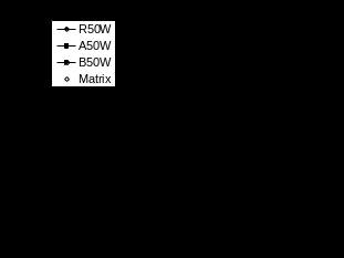
The absorption of fluids in polymer materials often follows the predictions of Fick’s Law [23,24], where the mass of fluid absorbed initially increases linearly with the square root of time and then absorption rate gradually reduces until an equilibrium, or saturation, plateau is reached. The results of the fluid absorption experiments are summarised in Figures 1 which presents the data as a percentage change in mass versus the square root of absorption time. Figure 1a-b presents the data for the polymer and the two composite systems absorption in water at 50°C and 70°C. Under these conditions, both the polymer and composite samples appear to exhibit the main aspects typical of Fickian diffusion with a rapid initial uptake of liquid (linear with t1/2) followed by a slow approach to an equilibrium absorption level. The water uptake by the composites is significantly less than that of the resin. It seems reasonable to assume that the glass fibers do not account for any of the weight increase seen during the hydrolysis treatment [12-18] and that the weight increase observed with the composites is solely due to weight changes of the polymer matrix. By dividing the composite weight increase by the average matrix content it is possible to examine the composite matrix weight change during the conditioning experiments and these data are also shown in Figure 1. The estimated average composite matrix equilibrium water content is significantly less than the unreinforced polymer value, with a larger difference observed at 70°C. This restriction of the matrix equilibrium fluid uptake in comparison to the unreinforced polymer has been observed in similar systems under a range of conditions and has been related to the restriction of swelling due to the fibers present [17,18]. It can also be seen in Figure 1 that there is no significant difference between the absorption results obtained with two composite systems A and B at either conditioning temperature in any of the three test fluids. Comparing the results in Figure 1a and 1b it can be seen in that the rate of water uptake is related to temperature with higher temperatures resulting in faster water absorption rates. However the equilibrium water uptake appears to be independent of temperature in this range. It has been shown that the diffusion coefficients for water in PA66 obtained from a simple one dimensional Fickian analysis of the data in Figures 1a-b were in good agreement with previously published values [20].
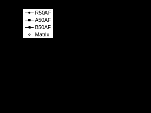
The results for the absorption of ethylene glycol by both polymer and composite samples presented in Figures 1c and 1d clearly do not follow a simple Fickian diffusion process. For both polymer and composites the rate of ethylene glycol uptake is related to temperature. However after 900 hours none of the samples in the EG had appeared to reach a final equilibrium value at either test temperature. Once again the fluid uptake by the composites is seen to be significantly less than that of the resin due to the presence of the non-absorbing fibers and again the estimated value obtained for the matrix absorption was well below the values obtained for the polymer alone. Figures 1e and 1f present the absorption data for the samples in the 50:50 water ethylene glycol antifreeze mixture. Both polymer and composite samples also appear to exhibit Fickian fluid uptake at 70°C. However, on closer examination the data in Figure 1f do not follow a pure Fickian trend but actually follow a pseudo-Fickian trend [18,20]. At 50°C there appears to be evidence of a two-step fluid uptake in both polymer and composite samples. The equilibrium AF fluid uptake of the samples at 70°C is significantly greater than that observed for water alone in Figures 1a and 1b. For both polymer and composites the rate of AF fluid uptake is related to the temperature and in the time range studied here it appears that the equilibrium AF fluid uptake is also dependent on the test temperature. However it is possible that the equilibrium value at 50°C may also reach that of the 70°C test if given sufficient time. Once again the AF fluid uptake of the composite matrix was significantly less than that of the resin value.
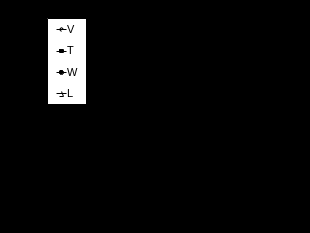
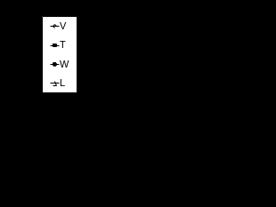
The conditioning also resulted in significant changes in the dimensions of the polymer and composite samples. The results of the swelling experiments are summarised in Figures 2 to 4 which present the data as a percentage change in volume (V), thickness (T), width (W), and length (L) versus the square root of conditioning time. Figure 2 shows the data for the three samples R,A,B swelling in water at 50°C and 70°C. Figures 3 and 4 similarly present the results for three materials in ethylene glycol and antifreeze mixture. The curves in Figure 2 for volumetric swelling in water follow similar trends observed for the weight increase data in water in Figure 1a,b. The volume change curves also appear to follow a typical Fickian trend with an initial steep linear increase followed by a gradual approach to an upper equilibrium value. The slope of the volume increase is greater at 70°C than at 50°C although, once again the equilibrium swelling of polymer and composites in water appears to approximately the same at both temperatures. However, significant differences can be observed when the individual dimensions of these injection molded bars are considered. It can be seen that the linear swelling of the PA66 samples is different when considering the T, W, L direction. These differences are considerably greater for the composite samples A and B. In this case the swelling in the T direction appears to account for approximately 60% of the volumetric swelling whereas the swelling in the L direction is negligible in most composite cases.
The volumetric swelling data in EG shown in Figures 3a-f clearly do not follow a Fickian trend for any samples at either temperature. The largest part of these volumetric swelling curves appear to show a linear increase (with t½) with a strong indication of a further increase in the slope of this increase at times greater than 600 hours at 70°C. Furthermore the level of swelling anisotropy is much greater for the resin samples in EG than in water. Overall, there appears to be considerably less swelling of all three materials in EG than in water, particularly at 50°C. This is also true for swelling at 70°C until at longer times the EG swelling increases strongly to approach the same level as water swelling by 900 hours conditioning time. The volumetric swelling curves for the AF mix in Figure 4 show similarities with the mass increase data in Figure 1e,f. At 50°C the data is clearly not Fickian whereas at 70°C the data is pseudo-Fickian. The rate of AF swelling is greater at 70°C and the level of swelling after 900 hours is also greater at 70°C, although it may be that swelling at 50°C has not reached its final level at that time. The linear swelling data reveal some anisotropy in the swelling of the resin sample and again a much greater level of anisotropy in the composites. Although the level of AF swelling is initially lower than that in water, by 900 hours conditioning time the AF swelling is approaching or in some cases (compare R70 data) exceeding the level of water swell.
The elastic behaviour of composite materials is often considered in terms of deformations caused by mechanical stresses due to physically applied loads. However, deformations are also produced by environmental changes such as temperature changes and moisture absorption. The relevant physical parameters which quantify these phenomena are the coefficients of thermal expansion (CTE) and the coefficients of swelling. Although CTE’s are the more familiar of these coefficients, these two phenomena are similar and can be treated in a similar fashion. The swelling coefficient () is defined as =/C where =D/D the dimensional strain and C=W/W the mass of absorbed moisture per unit mass [17,18,25]. Similarly to thermal expansion it is possible to define coefficients of linear swelling (TWLin the T,W,L directions of the sample and a volumetric swelling coefficient (V.
Figure 5 shows an example of the volumetric and linear swelling plotted against mass increase for composite system A conditioned in AF fluid at 50°C. It can be seen that excellent linear relationships are obtained for the change in dimensions for both composite and polymer samples and least squares fitted lines are also shown in Figure 5. The slopes of these lines give the respective swelling coefficients for that system under those particular conditions. Table 1 presents a summary of the complete analysis of the linear and volumetric swelling coefficients in the three test fluids of the three samples at the two temperatures used in this study. It is clear from the data in Table 1 that there are major differences in the linear and volumetric swelling coefficients between the composites and the unreinforced PA66 polymer. However, as might be expected, there were no significant differences observed in the swelling coefficient for any particular conditioning fluid. Neither was there any significant difference observed in the performance of the two composite systems at these relatively low conditioning temperatures. Consequently, it was deemed reasonable to reduce the volume of data by averaging the data to swelling coefficients for polymer and composite, for the three fluids. These averaged values are presented in Figure 6. It is clear from the data in this Figure that the volumetric swelling of these materials is not equally divided in the three sample dimensions. The directional dependence of CTE’s in fiber reinforced composites is well known and is attributed to the restriction of expansion in the fiber direction due to the much lower CTE of the fiber compared to the polymer matrix [17,26,27]. In a similar fashion it can be assumed that =0 for glass fibers and so the presence of fibers will restrict the matrix swelling in the fiber direction and consequently increase the swell normal to the fiber direction due to Poisson’s effects in the matrix. There is little degree of out of plane fiber orientation (through the thickness) in these injection molded samples [18,28] and consequently a higher swelling coefficient is observed in the thickness as compared to the width where the fibers in the “core” of the molding have a somewhat more random in-plane orientation. Since the highest level of fiber orientation is in the flow direction in the mold, very low levels of swell in the length direction of the composite samples can be expected. It can be seen from the values of in Figure 6 that these expectations are borne out in the data. It is interesting to note in Figure 6 that some direction dependent differences are also observed in the values for the molded PA66 polymer resin samples. This may well be indicative of some orientation at the molecular level in the injection molded polyamide polymer. It is also apparent from the data in Figure 6 that the values of for the AF mixture are lower than those for water and EG. This pattern is observed for both polymer and composites.
It can easily be shown that, if the polymer or the composite matrix swells by the volume of the absorbed liquid then a value of V = X /A is obtained for the slope of the lines in Figure 5, where X andA are the densities of the unconditioned sample and the absorbed fluid. This is the explanation for the systematically lower values of V obtained for the unreinforced polymer (X =1.117) in comparison to the composites (X =1.337) in Figure 6. Although it is not certain that the PA66 polymer or matrix absorbs fluid containing the same ratio of water/glycol from the AF conditioning, it would be expected that the value of A for the AF absorbed fluid would lie somewhere between that of water and EG. Consequently it might be predicted that the value obtained for V in the AF experiments should also lie between the value obtained for water and EG. This does not appear to be the case in Figure 7. This phenomenon is under further investigation and will be reported on in a future paper [20]. As discussed above, assuming that there is no significant dissolution of the samples over the range of conditioning temperature, it should be possible to overlay swelling data for a polymeric material conditioned in the same fluid at different temperatures. Figure 8 shows the data from this study on composite volumetric swelling compared with results from a previous study on almost identical injection molded glass reinforced PA66 composites conditioned in water:glycol antifreeze mixture at the much higher temperatures of 120°C and 150°C. It can be seen that there is excellent correlation between the results of these two studies and that it should be possible to predict the swelling performance at higher temperatures from data generated at moderate conditioning temperatures.
Conclusions
This study of injection molded glass-fiber reinforced polyamide 66 composites has revealed that hydrothermal conditioning in water, ethylene glycol, and water-glycol antifreeze mixture results in significant changes in the weight and dimensions of these materials. All materials showed a weight increase due to hydrothermal conditioning at both 50°C and 70°C. Water absorption followed a simple Fickian diffusion process whereas EG absorption followed a more complex process. The water-glycol antifreeze mixture appeared to follow a pseudo-Fickian diffusion process. It was noted that the presence of the glass fibers reduced the fluid uptake by an amount significantly greater than would be expected from a simple scaling with the polymer content of the composites. A strong correlation was observed between the swelling of these samples and the level of fluid adsorption. The time dependent volumetric swelling followed very similar patterns as for weight increase. It was not apparent that changing the glass fiber sizing affected the dimensional stability of the composites under the relatively mild conditions of this study. Although the PA66 resin showed reasonably homogeneous swelling, the composites exhibited different levels of swelling depending on direction. These effects were well in line with the known effects of fibers on restriction of the matrix deformation (mechanical, thermal or moisture swelling) in the fiber direction. The volumetric swelling of the composites in this study correlated well with results previously obtained at much higher conditioning temperatures.
Acknowledgement
The author gratefully acknowledges the support of 3B Fiberglass, Battice, Belgium with the preparation and molding of the materials used in this study.
References
N. Sato, T. Kurauchi, S. Sato, and O. Kamigaito, J. Compos. Mater., 22, 850 (1998).
A.Hassan R.Yahya, A.H.Yahaya, A.R.M.Tahir and P.R.Hornsby. J.Reinforced Plastics and Composites, 23, 969 (2004).
J.L.Thomason, Polym.Composites 27, 552 (2006).
J.L.Thomason, Polym.Composites 28, 331 (2007).
B. Mouhmad, A. Imad, N. Benseddiq, S. Benmedakhène and A. Maazouz, Polymer Testing, 25, 544 (2006).
E.Carlson and K. Nelson, Automotive Engineering, 104, 84 (1996).
A.R.Harrison. Automotive Composite Components, Chapter 11 in Integrated Design and Manufacture Using Fiber-reinforced Polymeric Composites. Eds. M.J.Owen and V. Middleton Woodhead Publishing, 2000.
D.M.Bigg and V.Kanellopoulous, Journal of Thermoplastic Composite Materials, 8, 293 (1995).
J. Markarian, Reinforced Plastics, 51, 36 (2007).
J.Gavenonis and J.E.McIlvaine, Society of Automotive Engineers Technical Paper, 2009-01-1297 (2009).
D.Valentin, F.Paray, B.Guetta. J.Mater.Sci., 22, 46 (1987).
Z.A. Mohd Ishak and J.P. Berry, J.Appl.Polym.Sci., 54, 2145 (1991).
N. Takeda, D. ZY. Song, K, Nakata, Adv. Composite Mater. 5, 201 (1996).
A.Bergeret, I.Pires, M.P.Foulc, B.Abadie, L.Ferry, and A.Crespy, Polymer Testing 20, 753 (2001).
N. Jia, H.A.Fraenkel and V.A. Kagan, J.Reinforced Plastics and Composites, 23, 729 (2004).
I. Carrascal, J.A. Casado, J.A. Polanco, F. Gutiérrez-Solana, Polymer Composites, 26, 580 (2005).
J.L.Thomason, Polym.Composites 28, 344 (2007).
J.LThomason and J.Z.Ali. Composites Part A 40, 625 (2009).
J.LThomason, J.Z.Ali and J.Anderson. Accepted Composites Part A (2010).
J.L.Thomason and G.Porteus. Submitted Composites Part A (2010).
T.A. Coakley, J.E. Rubadue, C.E. Forman and R.A. Schweizer, United States Patent 4,255,317 (1981)
J.L.Thomason and L.J.Adzima. Composites Part A 32, 313 (2001).
J.Crank and G.S.Park. (eds) Diffusion in Polymers, Academic Press, New York, 1968.
C.E.Rogers. ‘Permeation of Gases and Vapours in Polymers’ Chapter 2 in Polymer Permeability, ed. J Coymn, Elsevier Applied Science Publishers, London, 1985
B.W.Rosen in Engineered Materials Handbook, Volume 1 Composites, ASM International, 1987
R.A.Schapery, J.Composite Materials 2, 380 (1968)
J.L.Thomason and W.M.Groenewoud, Composites Part A 27A, 555 (1996)
J.L.Thomason, Compos.Sci.Technol., 61, 2007 (2001).
Tables
|
|
Swelling Coefficients |
|||
|
Sample |
Volume V |
Thickness T |
Width W |
Length L |
|
R50W |
0.981 |
0.411 |
0.290 |
0.260 |
|
R70W |
0.992 |
0.422 |
0.313 |
0.250 |
|
R50AF |
0.817 |
0.385 |
0.272 |
0.148 |
|
R70AF |
0.942 |
0.382 |
0.303 |
0.232 |
|
R50EG |
0.928 |
0.459 |
0.303 |
0.157 |
|
R70EG |
0.886 |
0.410 |
0.279 |
0.181 |
|
|
|
|
|
|
|
A50W |
1.150 |
0.644 |
0.407 |
0.082 |
|
A70W |
1.148 |
0.699 |
0.411 |
0.025 |
|
A50AF |
1.045 |
0.624 |
0.357 |
0.049 |
|
A70AF |
1.006 |
0.521 |
0.415 |
0.053 |
|
A50EG |
1.105 |
0.648 |
0.356 |
0.078 |
|
A70EG |
1.074 |
0.621 |
0.422 |
0.023 |
|
|
|
|
|
|
|
B50W |
1.126 |
0.610 |
0.424 |
0.076 |
|
B70W |
1.178 |
0.657 |
0.461 |
0.043 |
|
B50AF |
1.062 |
0.622 |
0.376 |
0.055 |
|
B70AF |
1.002 |
0.544 |
0.413 |
0.031 |
|
B50EG |
1.157 |
0.679 |
0.368 |
0.076 |
|
B70EG |
1.058 |
0.672 |
0.399 |
0.051 |
Table 1: Swelling coefficients of molded PA66 polymer and Composites A and B
List of Figures
Figure 1 Change in sample mass versus time
Figure 2 Swelling of samples in water (V-volume, T-thickness, W-width, L-Length)
Figure 3 Swelling of samples in ethylene glycol (V-volume, T-thickness, W-width, L-Length)
Figure 4 Swelling of samples in antifreeze mixture (V-volume, T-thickness, W-width, L-Length)
Figure 5 Example of determination of Swelling Coefficients
Figure 6 Average Swelling Coefficients for PA66 polymer (R) and glass fiber reinforced PA66 composites (C) in water (W) antifreeze mixture (AF) and ethylene glycol EG).
Figure 7. Comparison of glass fibre PA66 composite swelling in antifreeze mixture at various temperatures (* reference 17).
![]()
![]()


![]()
![]()

![]()
![]()

Figure 1 Change in sample mass versus time

![]()
![]()
![]()
![]()
![]()
![]()
Figure 2 Swelling of samples in water (V-volume, T-thickness, W-width, L-Length)
![]()
![]()
![]()
![]()

![]()

![]()
Figure 3 Swelling of samples in ethylene glycol (V-volume, T-thickness, W-width, L-Length)
![]()
![]()
![]()
![]()
![]()
![]()
Figure 4 Swelling of samples in antifreeze mixture (V-volume, T-thickness, W-width, L-Length)
Figure 5 Example of determination of Swelling Coefficients

Figure 6. Average Swelling Coefficients for PA66 polymer (R) and glass fiber reinforced PA66 composites (C) in water (W) antifreeze mixture (AF) and ethylene glycol EG).

Figure 7. Comparison of glass fibre PA66 composite swelling in antifreeze mixture at various temperatures (* reference 17).
Tags: conditioning in, higher conditioning, polyamide, conditioning, reinforced, swelling, during, glassfiber
- G UIÓN DE TELEMARKETING DE DDOS ADMINISTRADO BUENOS DÍASTARDES
- PUESTO QUE SOLICITA CONFIDENCIAL PARA USO EXCLUSIVO DEL ING
- TEACHING STATEMENT – JENNIFER D SMALL I BELIEVE THAT
- PRÁCTICAS PREPROFESIONALES FAQ 1 ¿CUÁNTOS CRÉDITOS DEBO TENER ACUMULADOS
- ARBEIDSLISTE SØMNAMESSA 2008 ONSDAG 15OKTOBER FØLGENDE MØTER KL
- 1 SINIF TIBBI VE KLINIK BECERILERI VE GRUP LISTELERI
- SUBCHAPTER 32H ‑ EMERGENCY MEDICAL SERVICES ADVANCED LIFE SUPPORT
- TEMA 7 TRASTORNO POR DÉFICIT DE ATENCIÓN E HIPERACTIVIDAD
- CONSEGUIR TRABAJO EN ALEMANIA SITIOS WEB ÚTILES PARA ENCONTRAR
- ZAKON O IDENTIFIKACIJI I REGISTRACIJI ŽIVOTINJA ZAKON JE OBJAVLJEN
- UFFICIO STAMPA 30062021 OPERA PASSIONE BELLEZZA E TECNOLOGIA IN
- NARODOWY FUNDUSZ ZDROWIA WNIOSEK O WYDANIE DOKUMENTU S1 CZŁONKOWI
- 埃及政府指定接待中国旅游团的旅行社名单 (233家) 序号 旅行社名称 地址 联系方式 1 3 A
- ENZYME SUBSTRATE COMPETITION IN A DEVELOPING EMBRYO YOOSIK KIM
- 11 ¡BIENVENIDOS A LA VI CONVENCIÓN INTERCONTINENTAL DE PSICOLOGÍA
- STOKED THE RISE AND FALL OF GATOR PRESENTS STOKED
- LA DECADENCIA DE LA SANIDAD CATALANA LA SANIDAD CATALANA
- 5 TOWN OF WEST BRIDGEWATER BYLAW FEE TRANSMITTAL FORM
- PRIZNANJA IN UGOTOVITVE OČETOVSTVA TER POSVOJITVE OTROK PRIZNANJE OČETOVSTVA
- STAND 1522017 FORMBLATT A ZUR ANERKENNUNG EINER SONSTIGEN PRAKTISCHEN
- 27 ABSTRAK EVALUASI PENETAPAN HARGA POKOK PRODUKSI CRABMEAT (STUDI
- bas01
- NA OSNOVU ČLANA 3033 ZAKONA O RADU («SLUŽBENI GLASNIK
- GIMNASIA DOMICILIARIA EN ESTOS MOMENTOSEN LOS QUE DEBEMOS SEGUIR
- FORM NRE4 COMPANIES REGISTRY NOTICE TO MINORITY SHAREHOLDERS –
- SACRAMENTO CITY UNIFIED SCHOOL DISTRICT PURCHASING AND WAREHOUSE SERVICES
- BOLETÍN TÉCNICO Nº 57 DEL COLEGIO DE CONTADORES CONTABILIZACIÓN
- SCHEDULE 1 STUDENT PLACEMENT PROGRAM PLACEMENT SCHEDULE ITEMS DESCRIPTION
- CALCULADORA GRÁFICA (TI82 TI83 Y TI83 PLUS) LOS NÚMEROS
- DARTMOUTH’S THAYER SCHOOL EXCHANGE PROGRAM WITH DUKE UNIVERSITY STUDENTS
JUNE 2003 THE UNITED NATIONS AND THE GLOBAL FUND
 Druk%20sprawozdania%20dla%20opiekuna%20prawnego%20osoby%20ca%C5%82kowicie%20ubezw%C5%82asnowolni...
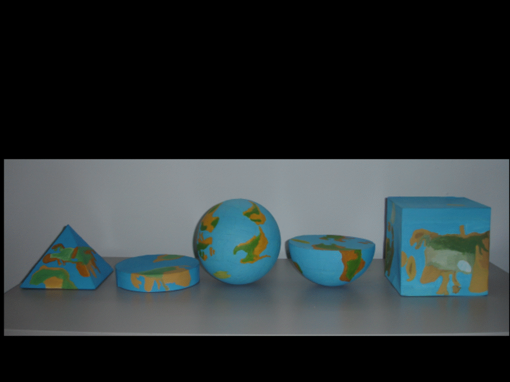 FIGURE 1 3D OBJECTS WITH GEOPHYSICAL SURFACE
 GESCHLECHTSORDNUNG VOM 26 OKTOBER 1675 ÜBERTRAGUNG (AUSFÜHRLICHE FASSUNG) DIE
[STS1529] PROVIDE QUICKFIX TO QUICKLY CREATE AUTOWIRED CONSTRUCTOR FOR
4 ACUICULTURA LA ACUICULTURA ES DEFINEIX COM LACCIÓ I
 TEACHER ALEXISS MANSILLA VENEGAS WWWMATEMATICOSINGLESWORDPRESSCOM GUIA DE ESTADÍSTICA 4ºMEDIO
101467 R DIR 446 3555 OTIR REF TRIBUTO
 ARCHITECTURAL CONCRETE PRODUCTS 1 GENERAL INFORMATION THE ORNAMENTAL PRECAST
 GINÉS CIUDADREAL NÚÑEZ TÉCNICAS DE COOPERATIVO TORNEOS DE JUEGOS
 5 HTTPWWWSEFHESVTIBINSHTMLEXENORMASNORMAY1HTMMAP RECOMENDACIONES PARA LA PREVENCIÓN DE ERRORES DE
 MOD 126 IMPUESTOS SOBRE VEHICULOS DE TRACCION MECANICA
 REF ID 2393 NEUTROPENIA AND FEVER IN CHILDREN WITH
 PRESTARIUM 5 MG TABLETKI POWLEKANE SKŁAD POSTAĆ JEDNA TABLETKA
PROGRAMA DE MOVILIDAD DOCENTE A UNIVERSIDAD POLITÉCNICA DE CATALUÑA
PRIMERA LECTURA ANTIGUO TESTAMENTO 1 GÉNESIS 1262831A DIOS LOS
 TEMA 8 WORD 2000 AVANÇAT (1ª EDICIÓ) JUNIO DEL
ESPAÑOL (LOLÓ JENNEPIN) « ¿PODRÍA DAR LA CLASE EN
 150519hawpolicyen
PUR110215 REQUEST FOR INFORMATION (RFI) PROVISION OF A JOB