11AAU CUBESAT BRIEF DESIGN DESCRIPTION THE MAIN PURPOSE
11AAU CUBESAT BRIEF DESIGN DESCRIPTION THE MAIN PURPOSE
1
1.1AAU CubeSat Brief Design Description
The main purpose of the AAU CubeSat project is for the involved students to achieve a great deal of knowledge about designing and constructing space worthy technology, but the real mission of the AAU CubeSat is to take pictures of the surface of the Earth and particularly of Denmark by using the on-board camera. Later on the pictures can be used for different purposes, e.g. to track the growth of algae in the seas surrounding Denmark and as a public outreach mission by letting the general public vote for a target that the camera shall photograph.
The images recorded by the satellite will later be transmitted to the ground station, located at Aalborg University, from where they will be distributed over the Internet and made accessible for the general public.
Several success criteria have been defined. A basic success criterion in this case is for students, to develop and build a satellite, which will be able to survive the launch and the hazardous environment in its orbit. Another success criterion is the establishment of a communication link with the ground station allowing satellite status data to be retrieved and analysed.
The final success criterion is to point the on board camera towards a specific target on the ground, take an image and to send this data down to the ground station.
To summarize the above, the mission’s success criteria are as follows:
That the involved students have achieved useful knowledge of space technology.
That communication is established with the satellite and housekeeping information is retrieved.
Take and download any picture.
Test ACS performance.
Take pictures of certain locations on earth.
(Take pictures of celestial objects and experiment with the various subsystems.)
The AAU CubeSat project consists of two major parts: satellite and ground station.
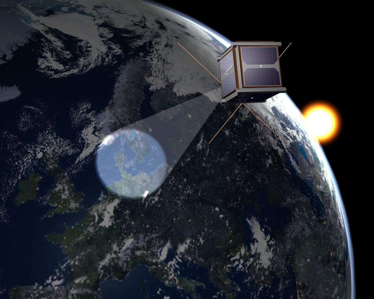
Figure xxx: Animation of AAU CubeSat in orbit.
The satellite itself consists of 6 modules: OBC (On Board Computer), ADCS (Attitude Determination and Control System), COM (COMmunication and antenna), PSU (Power Supply Unit), CAM (CAMera) and MECH (mechanical structure, including solar panels and batteries). The electronic modules also include software for control of the individual modules. A figure of the conceptual design can be seen on figure XXX.
In general the different electrical subsystems are build as autonomous, systems that are able to fulfil their most basic functions without cooperation with the other systems. This means that it is possible to retrieve basic housekeeping information from the satellite with only the power supply and radio-module working.

Figure xxxxx: Overview of AAU CubeSat
However nominally, with all subsystems working, the different subsystems will communicate through an I2C-bus. Then all satellite activities will be controlled from the OBC, which performs the following tasks:
Collects comprehensive housekeeping information from all subsystems and stores it for download when contact with the ground station has been established
Performs basic health-monitoring and acts to prevent battery exhaustion
Maintains the flight-plan and distributes events to the target subsystem, e.g. a take picture command for the camera
Handles the protocol for communication with the ground station and is responsible for carrying out all commands sent from ground.
Performs the attitude determination algorithms
Below in figure XXX is a picture of the fully functional engineering model satellite shown. A more detailed description of the Design of AAU CubeSat is enclosed as Appendix B
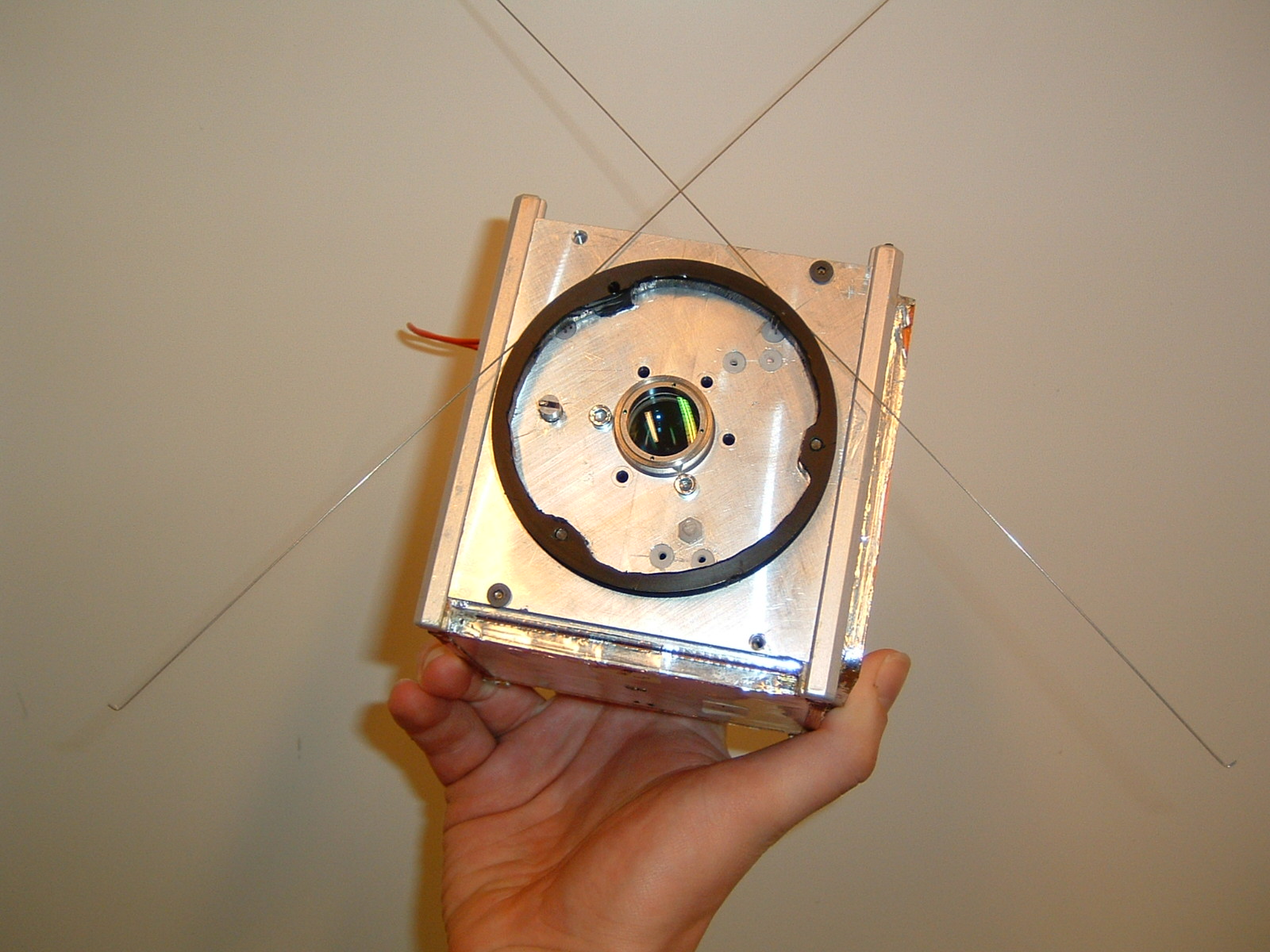
Figure XXX: The prototype AAU Cubesat
1.2Appendix B
The AAU Cubesat is divided in to a mechanical part and an electrical part.
The electrical subsystems of the satellite are controlled from a central on board computer (OBC) based on a C161PI micro controller from Infenion. It features a 16-bit CPU providing 16 Megabytes of Linear Address Space. The OBC uses three types of memory. A RAM module (4 MB) for picture data, dynamically allocated memory and buffers. A ROM module of 512kB for initial flight-software and 256kB of FlashRom used to upload new software after the satellite have been deployed in orbit. The OBC has the option of booting either on a PROM with the original software the satellite was launched with or on FLASH-ROM with contains new software uploaded to the satellite from the ground station. This boot selection is controlled by the PSU by a special algorithm, which continuously tries to boot the OBC from either PROM or FLASH until it has been successfully booted
The communication between the OBC and the other electrical subsystems are carried out by means of an I2C-bus, which connects the Power Supply Unit, the Attitude Determination and Control and The Camera subsystems. The Communication Unit is connected directly to the OBC though a parallel interface. The command interface to the camera is the I2C-bus, but when the picture is taken it is moved directly into the RAM of the OBC by a DMA interface. During this time the C161 MCU of the OBC is disabled from the databus and executes camera control code from an internal RAM-space of 2kb. The connection between the subsystems can be seen on figure B1:
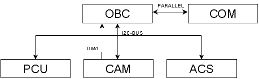
Figure B1 Basic overview of the subsystems in the AAU Cubesat
The software on the OBC is approximately 150kb of code, which controls the actions of the satellite based on a flightplan uploaded from the ground station and autonomously reacts to situations that may arise in orbit. It also collects and store housekeeping information from all subsystems and logs everything that happens on the satellite to a central satellite log.
It also:
Controls the mode of operation on the satellite, i.e. low power mode etc.
Calculates the attitude of the satellite with regards to the sun based on sensor data from the ACS subsystem.
Manages communication with the ground station regarding both low level control of modem and high level control of data protocol.
Operates the camera.
PSU:
The power supply consists of solar cells, batteries, two power converters, a number of protection circuits for users and a small micro controller.
The solar panels are the only source of power on the satellite and are placed on 5 of 6 sides of the satellite in pairs on the sides of satellite, which gives a total of 10 solar cells on the satellite. They are triple-junction cells with an efficiency of 28% and measure 68.96 x 39.55mm. The satellite will receive an average of 1.4 W from the solar cells, which is 1/30 of the power used in a normal light bulb and therefore the entire satellite has been designed to use as little power as possible.
The four on board batteries are developed and sponsored by the Danish company DANIONICS and will provide energy when the satellite is eclipsed or whenever the power use exceeds the power input from the solar cells, this will e.g. happen when the radio is transmitting. The batteries are a special kind of mobile phone batteries of 940mAh each and have a practically flat shape – they are however not able to withstand the vacuum in space and this has been solved by simply pressing the batteries in between two aluminum plates, simple but functional (see figure B2)
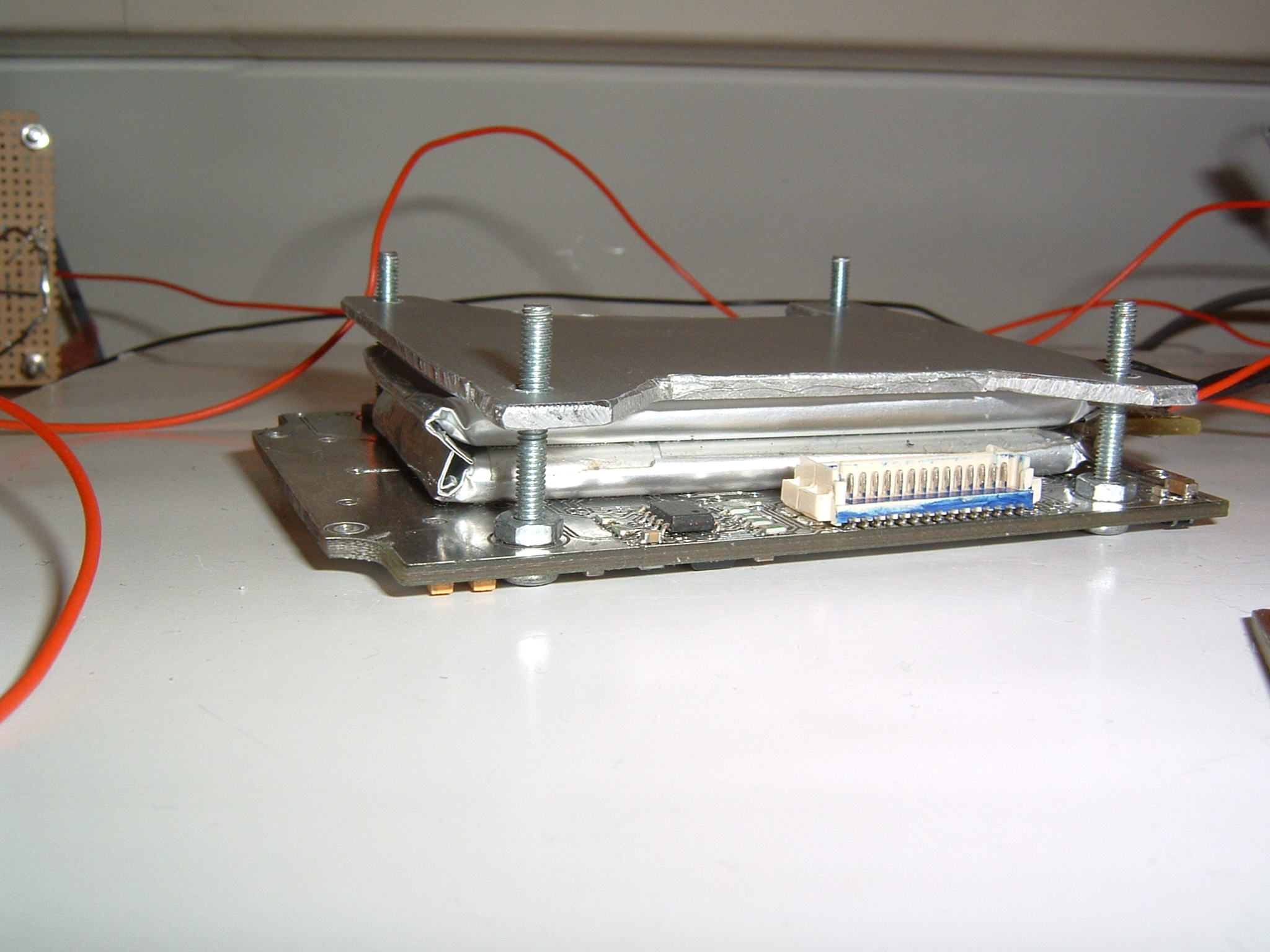
Figure B2: The mounting of the batteries.
The basic function of the power supply is to take power from the solar cells and move it both to the batteries and to the different subsystems. This done by utilizing a maximum power point tracking algorithm (MPPT) which is a way of getting the maximum power out of the solar cells at all times.
The power supply also functions as a watchdog for the rest of the satellite and ensures that short circuits caused by radiation in the satellite (Latch-up) are handled by rebooting the impacted subsystem. It is the most basic subsystem on the satellite and has therefore been designed with a number of different ways to make sure that it will continue to run no matter what happens. All variables in the software is saved in two places and each time one is read it is compared to the other and if there is difference a single event upset from radiation has happed and the PSU reacts to this. Also the power supply is able to continue to operate with the most important and basic functions entirely without the micro controller.
The basic schematic for the power supply is shown in figure B3 below.
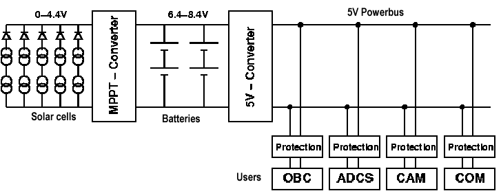
Figure B3 Basic overview of the PSU
COM:
In order to receive commands from the ground station as well as for transmitting the on board status and the images recorded during flight, an on board communication unit is used which will communicate with ground by using radio amateur frequencies. The COM unit of the satellite consists of two parts: a modem part and a radio part where the modem part is developed at Aalborg University and the radio is provided by a Danish radio vendor. The radio amateur protocol AX-25 is used to provide error free communication to and from the satellite. The radio transmits with a power of only 0.5W, which is about 1/4 of the power a normal mobile phone transmits with – the reason for the low transmitting power is to save power on the satellite.
The frequency for the satellite is in the 70cm amateur band, which is coordinated by the AMSAT association, and they have advised the frequency of 437.450MHz for use in the project.
T he
antennas on the satellite will be deployed after the satellite is
released from the launch vehicle – the antennas is fastened by
standard fishing wire and is deployed by heating two small pieces of
resistance wire which melts the fishing wire – see figure B4
below.
he
antennas on the satellite will be deployed after the satellite is
released from the launch vehicle – the antennas is fastened by
standard fishing wire and is deployed by heating two small pieces of
resistance wire which melts the fishing wire – see figure B4
below.
Figure B4: The antenna release system where the antennas are wound around the black ring.
The fishing wire can just be seen going past the resistance wire.
ADCS:
To be able to take images of the Earth, an attitude determination and control system is required. It will point the camera towards the correct target for imaging and for communication. Furthermore it will point the camera away from the sun and point three of the satellites sides with the solar panels towards the sun to ensure a maximum power input.
To control the satellites attitude in orbit three coils are used, which are mounted on three of the satellites sides perpendicular on each other. These will generate magnetic fields, which interact with the Earth’s magnetic field, and hereby change the attitude of the satellite.
To determine the satellites attitude two types of sensors are used. A magnetometer, build up with components from HONEYWELL, to provide information on the direction of the magnetic field of the Earth, and sun sensors. These sun sensors are basically planar photo diodes placed on each side of the satellite to measure the intensity of the incoming sunlight. The solar sensors and coils are shown on figure B5 below.

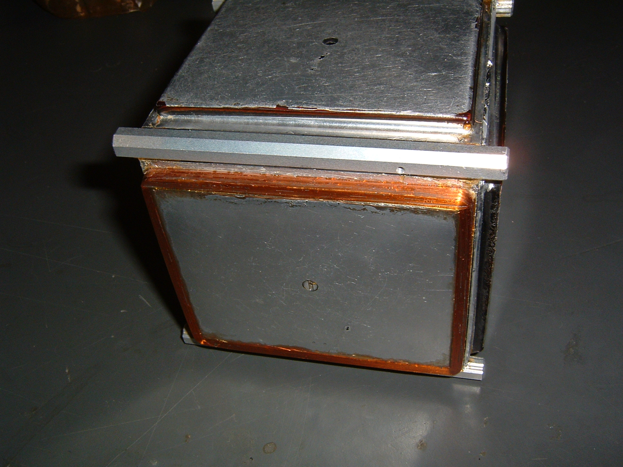
Figure B5 Solar sensors to the left and a coil on the side of the satellite to the right
CAM:
The
main payload for taking the images of Denmark is the on board
camera.
It is in this case a digital CMOS camera chip based on a
Kodak 1.3 megapixel kac1310, which has been provided by the Danish
company DEVITECH.
It will take images of the ground with a field of view of about 150 x
115 km and a resolution of 1280 x 1024 pixels with a color depth of
24bit, which gives bayer format pictures of about 1.3MB.
The
lens in front of the CMOS camera chip is handmade with a diameter of
2cm at a length of 5cm and a focal length of 40mm – see figure
B6 below. The lens system is real precision work – it has been
made with precisions of 1/1000 mm and should therefore be able to
produce a very sharp picture in space.

Figure B6: AAU Cubesat camera with spare lenses.
In flight it is possible to control exposure time, gains for the individual RBG colors, overall colorgain and size of picture. When a picture is taken it is possible first to download a thumbnail (160x128) of the real image (1280x1024) to determine if the picture is over- or underexposed before downloading the entire picture.
A mathematical model has been made of the camera before launch and by using this on the downloaded picture it is possible to correct different kinds of noise and distortions in the pictures. Also on ground it is possible to adjust by making better color contrast, sharpening the picture and so on.
Ground Station:
The ground station of the AAU Cubesat is placed on the university roof and consists mainly of two cross yaegi antennas with a gain of 18 dB and a motor to positions the antennas towards the satellite. A standard amateur data radio and a modem similar to the one on the satellite are used to receive the data, which is processed in a PC. This PC also stores all data to and from the satellite in a database, tracks the position of the satellite and controls the communication.
The ground station is capable of operation almost completely autonomously and during normal operation only the creation of new flight plans for the satellite requires human interaction.
MECHANICAL:
The mechanical design has been created around a frame of aluminium, which has been milled from one solid block of aluminum. This way a very strong and still quite light frame can be achieved. The frame consists of 4 rails - which are used to slide the satellite in/out of the P-POD - with connecting pieces between them. On these pieces the subsystem circuit boards are mounted with screws. Below in figure B7 a picture of the frame is shown.

Figure B7: The AAU Cubesat frame.
On the outside of the frame the solar cells and the coils for attitude control are mounted but not directly on the frame. Instead they are placed on carbon-fiber plates. These plates are glued on the frame and the solar cells and coils are glued onto the panels.
Tags: brief, design, 11aau, description, cubesat, purpose
- Pctwg114 Page 3 Wipo e Pctwg114 Original English Date
- ACTIVIDAD DE TUTORÍA LOS PREJUICIOS 1 OBJETIVOS 11EXPERIMENTAR
- 3 TEISMŲ TARYBA NUTARIMAS DĖL TEISĖJŲ SVEIKATOS PATIKRINIMO TVARKOS
- SECTION COVER PAGE SECTION 07 21 16 20110815 NON‑RIGID
- WWWREPRESENTANTESLACENTRALCOM MOLLY MALCOLM WEBSITE HTTPWWWMOLLYMALCOLMCOM EXPERIENCIA PROFESIONAL TEATRO OBRA
- FINDINGS AND DECISION FILE NUMBER LM01188 APPLICANT FR
- ANÁLISIS SÍSMICO DE EDIFICIOS POR COMPUTADORA 17 INTRODUCCIÓN
- AOP CONSIDERA NECESARIA LA REVISION DE LOS DERECHOS DE
- WARNING THE FOLLOWING INFORMATION
- FORMULARE FORMULAR NR 1 GARANŢIE DE PARTICIPARE FORMULAR
- 1 03072007 RJEŠENJE MINISTARSTVA ZAŠTITE OKOLIŠA PROSTORNOG UREĐENJA I
- ZAŁĄCZNIK NR 5 WZÓR NAZWA PODMIOTU REALIZUJĄCEGO ŚWIADCZENIA
- 5 THE ENVIRONMENTAL STUDIES INTERNSHIP NOVEMBER 2020 A GOOD
- FORM TH3 INTERNAL 194 MASTER PROGRAMME OF STUDY (MUST
- REVIEW OF THE SMALL AMOUNT CREDIT CONTRACT LAWS –
- 19 SC 912 DISTRIBUTABLE (3) JUDGMENT NO SC 912
- VÄSTERÅS STAD 0 (2) INDIVIDUELLT FÖRBEHÅLLSBELOPP ANSÖKAN
- PROGRAMACIÓ FESTA MAJOR 2010 SANTA CRISTINA D’ARO
- SGREGIDEIIIDT 2 23 DE OCTUBRE DE 2007 84663 III
- MATEŘSKÁ ŠKOLA CHRASTAVA REVOLUČNÍ 488 – PŘÍSPĚVKOVÁ ORGANIZACE 46331
- 16 QUALIDADE NO EMPREGO E INOVAÇÕES TECNOLÓGICAS O CASO
- ALTERNATIVE ENERGY PROPOSAL POSTER STEPS 1 CHOOSE AN ALTERNATIVE
- SECTION 06 12 00 STRUCTURAL INSULATED PANELS 1
- LIBERTY GROUP LIMITED – AN AUTHORISED FINANCIAL SERVICES PROVIDER
- Triglav – Simbol Slovenstva r a z p i
- 6 REPRINTED FROM THE NADD BULLETIN VOLUME 11 NUMBER
- DISCURSO DANIEL WOLFF CEREMONIA MEDALLA DOCTORAL 2010 INTRODUCCIÓN COMO
- NA OSNOVU ČLANA 13 ZAKONA O KOMUNALNIM DJELATNOSTIMA (SL
- 2 KOLO PRIJÍMANIA NA BAKALÁRSKY ŠTUDIJNÝ PROGRAM PRIESTOROVÉ PLÁNOVANIE
- COMP NAMEBENTUK PERATURAN PEMERINTAH REPUBLIK INDONESIACOMP COMP NAMENOMOR NOMOR
UNIVERSIDAD NACIONAL AGRARIA LA MOLINA DEPARTAMENTO ACADÉMICO DE INGENIERÍA
 ZAVOD DR MARJANA BORŠTNARJA DORNAVA LJUBLJANA 11 8 2017
 DOC EPC37408DA (VERSION 03) 23 NOVEMBER 2012 KR SEPA
AL MINISTERO DELLO SVILUPPO ECONOMICO DIPARTIMENTO PER L’IMPRESA E
 FOOD SAFETY MANAGEMENT CONTACTS ROBIN BRUCE EMAIL ROBINJBENNETTSCOUK STEVEN
CHILDREN ENCOURAGED TO EXPRESS THEIR FEELINGS THE JORDAN
 NARODOWY FUNDUSZ ZDROWIA ………………………… ODDZIAŁ WOJEWÓDZKI WNIOSEK O REFUNDACJĘ
AHRC2814ADD1 AHRC2814ADD1 ADVANCE VERSION DISTR GENERAL 17 MARCH 2015
SUMMARY RECORD OF THE ACD BREAKFAST MEETING SUNDAY 18
 CANTATA PER A NARRADOR COR INFANTIL A UNA SOLA
COMMENT LA MÉTAMORPHOSE SIGNIFIETELLE ? INTRODUCTION ÉLÉMENTS POUR UNE
E DEFAM292 REV 0310 PERÍODO DE RETENCIÓN SEIS (6)
PROJECT COLDS AND FLU RECRUITMENT QUESTIONNAIRE BRAND JULY 2014
CAJA DE EMPOTRAR CON TAPA CIMA PRO DE 2
 (BZP383821718) ZAŁĄCZNIK NR 2 DO SIWZ FORMULARZ OFERTOWY OFERTA
INFORMÀTICA P5 PRIMER TRIMESTRE SESSIÓ 1 PRESENTACIÓ PARTS
PATVIRTINTA KATALIKIŠKOJO AUKLĖJIMO KONGREGACIJOS PREFEKTO KARDINOLO ZENON GROCHOLEVSKI 2006
 F ICHA DE INSCRIPCIÓN CAMPAMENTO DE VERANO 2016 HERMANDAD
HQ 966892 JANUARY 26 2004 CLA2 RRCRGC 966892 AM
 P RESSEMELDING KORT KONKRET OPPSUMMERENDE TITTEL INGRESSEN PRESENTERER HOVEDPOENGET
