WE HAVE A GREAT COSINE COLLECTOR DESIGN MUCH BETTER
1 WELCOME THERE IS A GREAT SIGNIFICANCE OF THE100 GREAT BLACK BRITONS IDEAS WHEN WERE THE GREAT
101 GREAT ESCAPES RENTAL AGREEMENT PG 6 OF 5
15 DECEMBER 2005 NO3 DEMOCRATIC REPUBLIC OF CONGO GREAT
190 GREAT DOVER STREET LONDON SE1 4YB 2ND JULY
1A) EDUCATION IN CZECH REPUBLIC GREAT BRITAIN AND USA
We have a great cosine collector design much better than that shitty Satlantic clusterfuck, and we wanted to build on it for the microradiometer based instruments
We have a great cosine collector design much better than that shitty Satlantic clusterfuck, and we wanted to build on it for the microradiometer based instruments.
… insert how good our PRR design is…
The PRR cosine collector uses an angled array of photodetector-filter assemblies (PFA) all oriented to view the center of the second diffuser (figure x).
Fig x
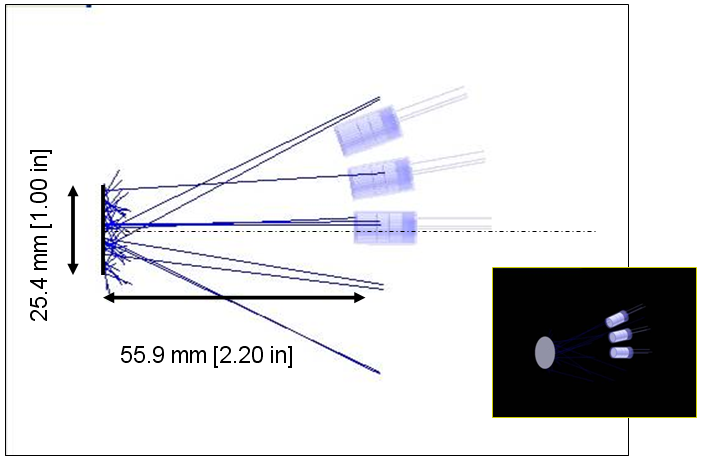
Figure 1. Ray trace diagram of the PRR cosine collector photodetector arranagement. This is the “baseline” configuration.
As the microradiometers are a complete assembly of filter, photodetector, and acquisition electronics and microprocessor, all packaged into a tube, it was not possible to have all oriented at the center of the secondary diffuser. To solve this problem we considered several options including quartz wedges attached to the microradiometer front end, and ended on using a plano-convex quartz lens as shown in figure 1. We worked with our consulting optical engineer (Brian Catanzaro) to determine the efficiency of using such a design and to understand how the filter bandpasses would be impacted by this alteration of the successful PRR design.
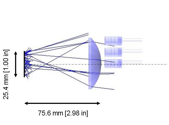
Figure 2. Sequential ray trace diagram from 1" rear diffuser through the lens of the 19 channel radiometer assembly into the radial spaced PFA. The top detector is called the edge detector as it is closest to the edge of the array, with the other two called the “middle” and “ctr” positions. In the full 19 channel version there are also intermediate positions to build out to the full count of 19.
The first issue we tackled was to choose the lens. First the PRR design was modeled using Zeemax to set the “baseline” design. The amount of flux reaching center, middle and edge detectors were determined. Additionally, since interference filters change their passband and out of band properties with angle of incidence, we determined the angle of incidences (AOI) for the baseline condition and plotted the distribution of angles of incidence through the filters. Figure 2 shows the results of one of these test runs. In all cases, the lower row is larger, and the edge pattern (lower right) is clearly distorted from the top. This distortion has two aspects, the wider pattern incidates a greater range of angles of flux on the detector (and thus through the filters). The vertical assymetry warns that if the cosine collector double diffuser arrangement results in an assymetrical distribution of flux on the second diffuser (and therefore out of that diffuser toward the detectors), then positon of the photodetector in the array may influence the resulting cosine response.
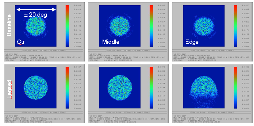
Figure 3. Comparison of traditional PRR optic design with one early proposed lensed design. The plot shows the radiance intensity distributions of the rays from the rear diffuser hitting the photodetector as a function of incidence angle. In these drawings the PRR ‘Baseline” is the top row and the lensed microradiometer candidate is the bottom row.
To better understand the implications of the assymetrical light collection using the lensed approach, we assembled a PRR cosine collector with an empty instrument body, and installed a macro lens with a digital camera to take an image of the second cosine collector while under “worst case” illumination (50cm, FEL source) in this case worst case was grazing illumination of the cosine collector (Figure 4).
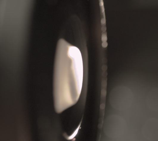
Figure 4. The collector was oriented at grazing incidence as a worst case example. Approximately 50% of the collector was illuminated due to a slight dome on the Teflon surface.
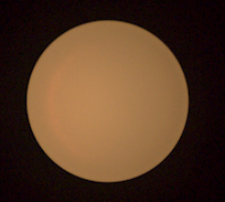
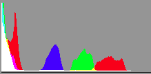
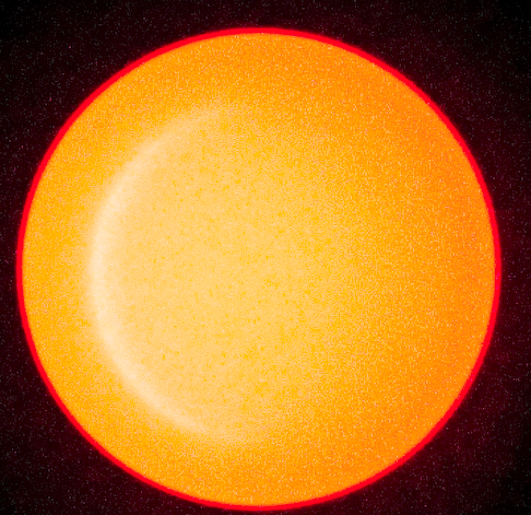
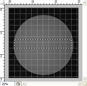
Images taken of the secondary diffuser of a PRR class instrument when the primary diffuser (the cosine collector) is illuminated at grazing incidence. Left image is natural without enhancement. Slight brightening is seen as an arc toward the left side. Middle image is its histogram by RGB channel. Right image is contrast enhanced to the maximum to accentuate the gradient. The ideal histogram would be narrow and Gaussian.
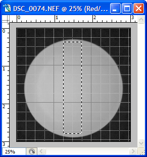
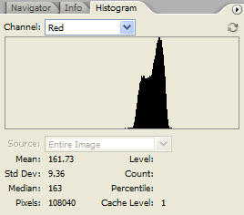
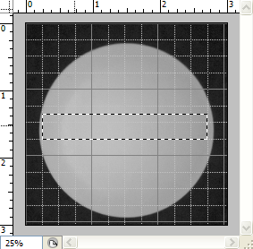
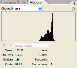
Taking horizontal and vertical sections through the image of the collector taken with the red channel only active. These sections have almost the same mean value but show different asymmetry. A semicircle of brighter light is shown on the left side, and this bright ridge is at 175 counts compared with the mean of 160 units for the disk.
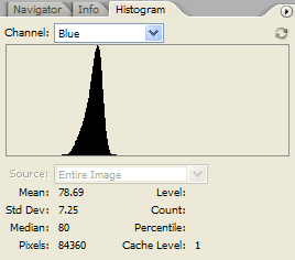
Considering the Blue channel only. Little asymmetry is seen.
These results indicate that, as expected, the red channel (longer wavelengths are less diffused than the shorter wavelengths due the diffuser being less diffuse in the longer wavelengths). To avoid cosine collector asymmetry, this indicates that we should position the longer wavelengths at the center of the array, and the blue-UV channels at the outer positions where the diffuser is nearly completely effective.
During the design phase we also explored using secondary baffles near the filter to constrain the angular distribution as shown in figure 6. This approach was discarded as causing too much asymmetry in the imaging of the secondary collector.
![]()
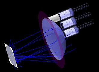
Figure 5. Ray trace diagram to explore use of baffles between the lens and PFA.
A variety of different focal length commercially available lenses were modeled using Zeemax and the results were evaluated by the amount of asymmetry in collection of flux from the second diffuser, the range of angle of incidence on the filter, and by the total throughput. The design arrived at after this testing is shown in figure 2. This design achieved approximately 20% better collection at the edges, and only slightly broader angle of incidence distribution (figure 7). The collection of flux from the rear diffuser is shown in figure 8.
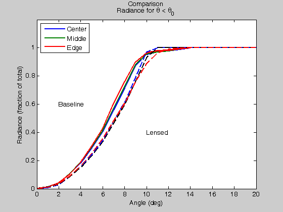
Figure 7. Fraction of the total flux collected (vertical axis) plotted against the angle of incidence on the filter. The baseline and final lensed designs are considered.
Figure 8. The lensed design imaging of the rear diffuser on the filter. The top three images are center, middle and edge array positions for the new design, while the lower three position are from the baseline design. The dimension of the dark blue square is 20° square. We note that the edge position shows some broadening and asymmetry, and these positions will be reserved for blue-UV channels where the effectiveness of the double diffuser is particularly effective.
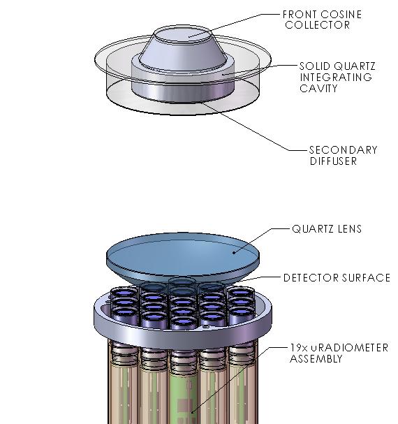
Figure 6. The completed design optical elements for the irradiance collector assembly shown without supporting parts.
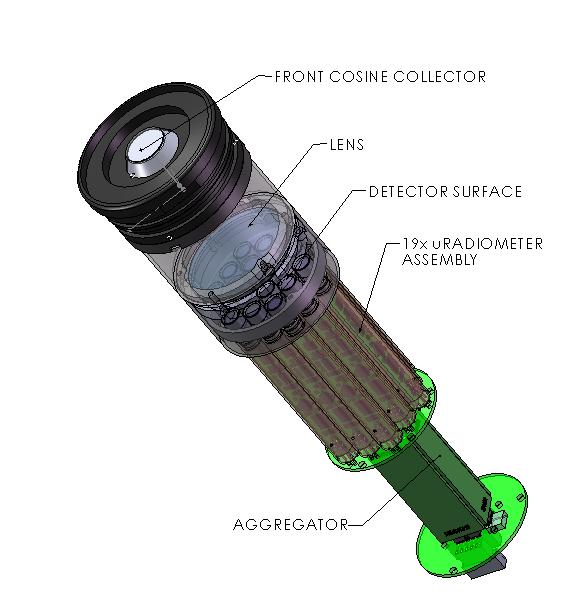
Figure 7. Views of the 19 channel, microradiometer-based irradiance radiometer
This all looks very good and confirms our choice of retaining the proven PRR cosine collector design. Of course, the real proof will be in full cosine collector characterization of production units after this SBIR is concluded.
Radiance Radiometer Design:
The radiance measuring microradiometer instruments are also based on earlier successful PRR designs, rescaled to a more compact size. The design is based on a clear pressure window (to withstand up to 350m depth) made of quartz, depending on the spectral range covered. The upper aperture plate along with the plate to detector plane distance determines the field of view, while the lower aperture plate and light traps reduce out of field stray light. The deliverable radiometer for this SBIR is built with a FOV of 9° half angle in air (6.7° in water).
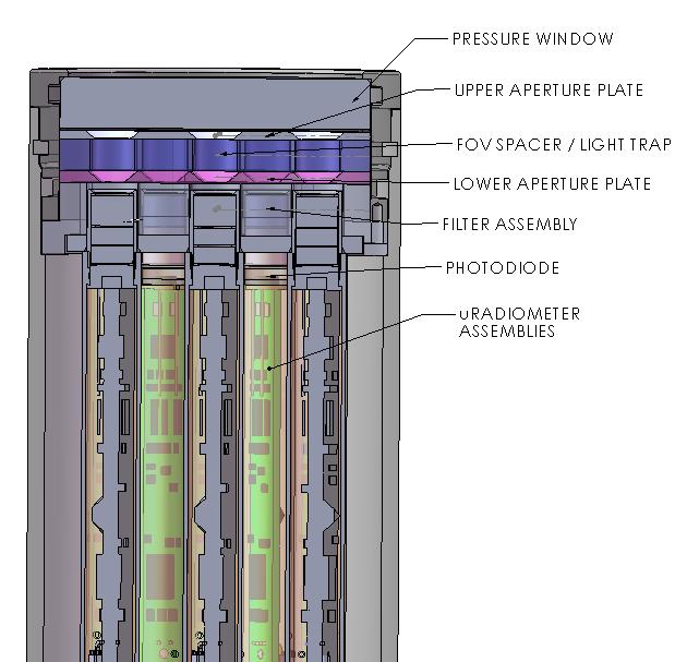
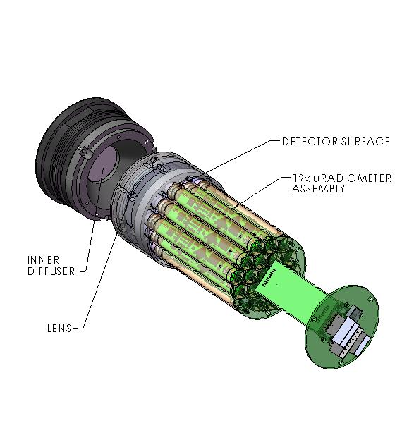
Figure 8. Cut away plane view of 19 channel Radiance radiometer based on microradiometers.
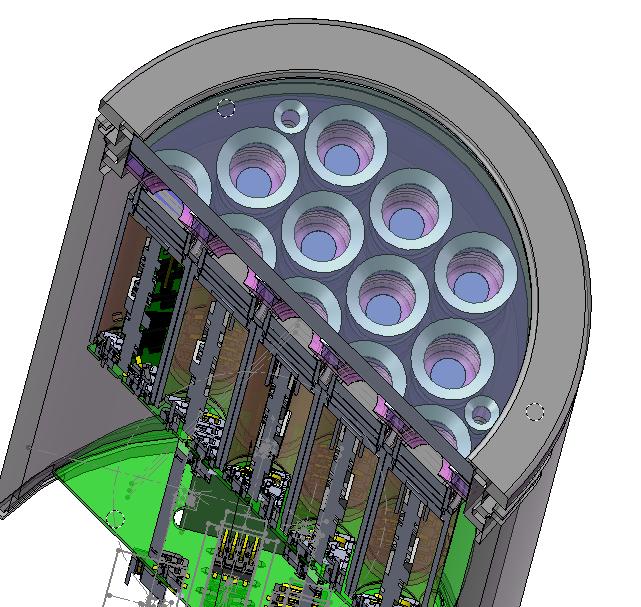
Figure 9. 3D cut-away view of the 19 channel radiance radiometer.
2 GREATER NEW HAVEN GREEN FUND INC CO CFGNH
2 the Structure of Great Power Politics 19631975 Marc
20 HENRY MERRILL PRATT TO UNDERSTAND THE GREAT IMPACT
Tags: better than, 20% better, design, great, cosine, better, collector
- ANALISIS SOCIOLOGICO EL GOLPE INAUGURÓ UNA FORMA ATROZ
- PRIMERI PRETVARJANJA MED RAZLIČNIMI ŠTEVILSKIMI SISTEMI SO 1 PRETVORI
- 4 GODKJENT 29 NOVEMBER 2012 REFERAT FRA STYREMØTE I
- [PXC3664] CLUSTERCHECK IN SOME CASES FAILS TO IDENTIFY CORRECT
- TŰZVÉDELMI MŰSZAKI IRÁNYELV TVMI TŰZOLTÓ KAPCSOK TARTALOMJEGYZÉK 1 ALKALMAZÁSI
- NA OSNOVU ČLANA 16E) I 23B) USTAVA BOSANSKOPODRINJSKOG KANTONA
- SMLUVNÍ VZOR KUPNÍ SMLOUVA Č 9115XXXXX UZAVŘENÁ PODLE §
- REGULAMIN CENTRUM SYMULACJI MEDYCZNEJ PRZY PAŃSTWOWEJ WYŻSZEJ SZKOŁY
- HARMONOGRAM ODBIORU ZMIESZANYCH ODPADÓW KOMUNALNYCH DLA FIRM I INSTYTUCJI
- FAKULTET ZA POSLOVNE STUDIJE – OAS ORGANIZACIONO PONAŠANJE (III
- CRITICAL LIMIT SUMMARY FOR BACON PROCESSING A TYPICAL HAZARD
- MISIÓN COMERCIAL A SENEGAL DAKAR DEL 26 AL 29
- REPUBLIKA HRVATSKA OSIJEČKO BARANJSKA ŽUPANIJA OPĆINA ERDUT OPĆINSKO POGLAVARSTVO
- CORE SKILLS WORKOUT CENTRAL IDEAS AND DETAILSHL NONFICTION “THE
- OFICINA DE GRADOS Y TÍTULOS INFORMACIÓN GENERAL APELLIDOS NOMBRES
- SINDIKAT POLICIJE KANTONA SARAJEVO P O S L O
- NATURAL SELECTION WORKSHEET NAME DATE PERIOD
- ALTO DEL CARMEN SEPTIEMBRE DE 2008 SR RODRIGO WEISNER
- CAPÍTULO TACTICA Y PRINCIPIOS OFENSIVOSDEFENSIVOS TACTICA SON TODAS AQUELLAS
- VIDEOFLUOROSCOPY OF SWALLOW (VFS) LEVEL 2 TRAINING PROGRAMME FOR
- ORDINE DE ZI LUCRĂRI A ŞEDINŢEI DIN 22 IULIE
- ZASTOSOWANIA PROFESJONALNE NUMER ZASTOSOWANIA NAZWA ZASTOSOWANIA ZIDENTYFIKOWANEGO POSTAĆ SUBSTANCJI
- COMISIÓN DE EUSKERA Y CULTURA EUSKERA ETA KULTURAKO BATZORDEA
- EL CASO ELEGIDO ES EL DE UN ALUMNO CON
- 49 OIL AND GAS PIPELINE STRATEGY OF A LANDLOCKED
- KURZGUTACHTEN PROJEKTARBEIT VERFASSERIN DER PROJEKTARBEIT STUDIENJAHRGANG STUDIENGANG STUDIENRICHTUNG FIRMA
- 16500 FELLOWSHIP IN BIOMEDICAL RESEARCH THE INBRE SCHOLAR
- PROYECTO DE DECLARACION LA CÁMARA DE DIPUTADOS DE LA
- CHARAKTERYSTYKA PRACY NA STANOWISKU PIELĘGNIARKI OPERACYJNEJ 1NAZWA STANOWISKA PIELĘGNIARKAPOŁOŻNA
- PÆDAGOGISK LÆREPLAN FOR SKOVVEJENS BØRNEHAVE TEMA LÆRINGSMÅL HVAD VIL
KOMUNIKAT KOMISARZA WYBORCZEGO W POZNANIU NA PODSTAWIE ART 24
SEATON VALLEY COUNCIL A COMMUNITY COUNCIL MINUTES OF A
PARIRSE COMO MADRE SE PODRÍA DECIR QUE CUANDO NACE
 ELEMENTOS DE FIJACIÓN DE USO AERONÁUTICO CÁTEDRA DISEÑO Y
2009 MASSACHUSETTS MARITIME ACADEMY FIFTH ANNUAL LT TRAVIS J
 ORDEN DEL CONSEJERO DE TURISMO CULTURA Y DEPORTES POR
AUTOLIQUIDACIÓN IMPUESTO SOBRE CONSTRUCCIONES INSTALACIONES Y OBRAS TASA POR
 MATLAB PROGRAM FILE ODE02M THE FIRST
 LANDRATSAMT EICHSTÄTT TEL 0842170445 DIENSTLEISTUNGSZENTRUM LENTING FAX 0842170480 BAHNHOFSTR
HOGYAN SZÓL HOZZÁNK ISTEN? HOGYAN TUDHATJUK MEG ISTEN AKARATÁT?
90 TRANSCRIPTIONS OF DOCUMENTARY INFORMATION RELEVANT TO THE VOYAGES
RETNINGSLINJER FOR TILSKUDDSORDNINGEN ” SKJEMA 2004 GLOBALE ENDRINGER NORSKE
УГОВОР БРОЈ ЗАКЉУЧЕН ДАНА 2017ГОД У КРАГУЈЕВЦУ
 MUHASEBE VE İŞLETME KAVRAMI MUHASEBE EKONOMIK FAALIYETLERDE
 TEHNISKĀ SPECIFIKĀCIJA 4 IEPIRKUMA DAĻAI IEPIRKUMĀ „BIROJA PREČU IEGĀDE
XVIII OGÓLNOPOLSKA OLIMPIADA WIEDZY O PRAWIE – ETAP CENTRALNY
RESTRICTIONS KNOW ALL MEN BY THESE PRESENTS THAT WE
KOLLÉGIUM 1 A KOLLÉGIUM STÁTUSA HELYZETE AZ ISKOLA SZERVEZETI
PLAN ZAJĘĆ LABORATORYJNYCH SPECJALNOŚĆ ANALITYKA I KONTROLA JAKOŚCI V
NZQA UNIT STANDARD 6936 VERSION 8 PAGE 5 OF
