OPERATING MANUAL FDY10HS BATTERY TESTER DECEMBER 2013 ZHENGZHOU MING
SEARCH AND RESCUE MODEL OPERATING PLAN A GUIDE1 THE OPERATING COMMITTEE OF UNITED STATES POWER SQUADRONS
112 REVISED 92011 CREDIT AND DEBT MANAGEMENT OPERATING STANDARDS
12 STEPS TO TECH HOST USING MAC OPERATING SYSTEM
20 MULTIAGENCY RISK ASSESSMENT CONFERENCING (MARAC) OPERATING PROTOCOL MULTIAGENCY
2623A WIS JI‑CRIMINAL 2623A 2623A OPERATING WHILE SUSPENDED CRIMINAL
OPERATING MANUAL
OPERATING MANUAL
FDY10-H/S Battery
Tester
December 2013
Zhengzhou Ming He Electronic Technology Co., Ltd.
Contents
1. Contact
Address: No.96 Rui Da Rd., Zhengzhou, China
Tel: 86-371-86106382
Fax: 86-371-86106382
Zip: 450001
E-mail: [email protected]
Website: www.mhinstek.com
2. Inspecting Package Contents
When you get a new FDY10-H/S battery tester, please inspect the instrument as follows:
2.1 Check if there is damage due to transportation
If the package is damaged, please retain them until the instrument and accessories are tested.
2.2 Check package contents
Contents of the case are as bellows, if the content does not match with the packing list or the instrument is damaged, please contact us.
|
|
FDY10-H battery tester |
FDY10-S battery tester |
|
The host |
1pc |
1pc |
|
High power aluminum resistance(1Ω,200W) |
4pc |
1pc |
|
DC 5V adapter |
1pc |
1pc |
|
Test wiring |
2pc(red and black) |
2pc(red and black) |
|
User manual(pdf) |
1pc |
1pc |
2.3 Check the machine
If the machine was damaged; did not work properly or failed to pass performance tests, please contact your dealer or our company.
FDY10-H/S battery tester is a new type instrument, which can detect the capacity of the battery, also can measure the discharge time and discharge AH of the battery. It is a new dual-function measuring device integrated with detection and measurement. FDY10-H battery tester adapts to the voltage range of 1V ~ 60V, FDY10-S adapts to the voltage range of 1V ~ 20V. They adapt to the batteries of different kinds and is mainly used to measure Ni-Cd, Li-Ion, Pb, Ni-Mh, Ag-Zn, LMP, Li-po, Pb, etc., with the discharge current range of 0.1A-10A automatic constant current.The discharge termination voltage of FDY10-H can be set between 0V ~ 60V, and FDY10-S can be set between 0V ~ 20V. In the discharge, the LED display the voltage, current, power, AH, time in real time. After finish discharging the battery, it will display the measurement results such as AH and discharge time .
Small size, light weight and portability;
The host and heating elements are separate,high stability;
Small measurement error and more accurate measurement results due to application of 4-wiring-system measurement mode
Availability for setting automatic slide show function to check operating states and parameters visually and clearly due to the display mode based on combination of the LED indicator light and the LED nixie tube;
Operation sound prompt and alarm for finish of discharge
Wider voltage detection range for the battery due to 2Wire and 3Wire detection modes
Automatic identification of 12V and 16V batteries
Rapid test function to detect the approximate capacity of a battery within 1-10min rapidly;
Constant resistance mode
FDY10-H is availability for battery pack of polymer lithium batteries, lithium iron batteries or lead-acid batteries, with the voltage of 12V, 16V, 24V, 36V and 48V;
FDY10-H:Series connection of power resistors (four 200W resistors at most), availability for automatic identification of resistance value, and flexible wiring modes.
|
Item |
Parameter |
||
|
Final discharging voltage of battery |
FDY10-H |
0.00V~60.00V |
|
|
FDY10-S |
0.00V~20.00V |
||
|
Time setting of rapid detection |
1~10min |
||
|
Discharge current of battery |
Battery voltage is less than 10V |
0.1A~10A |
|
|
Battery voltage is more than 10V |
0.4A~10A |
||
|
Voltage measurement |
Range |
FDY10-H |
0.00V~60.00V |
|
FDY10-S |
0.00V~20.00V |
||
|
Accuracy |
0.01V |
||
|
Error |
±0.5% |
||
|
Current Measurement |
Range |
0.00A~10.00A |
|
|
Accuracy |
0.01A |
||
|
Error |
±1% |
||
|
Measurement of Battery power
|
Accuracy |
0.1W |
|
|
Measurement of Battery capacity |
Accuracy |
Less than 100AH:0.01AH; More than100AH:0.1AH |
|
|
The maximum display value |
999.9AH |
||
|
Dimensions |
host (L * W * H) |
116×90×40mm |
|
|
aluminum resistance (L * W * H) |
165×60×30mm |
||
|
Weight |
host |
190g |
|
|
aluminum resistance |
450g |
||
|
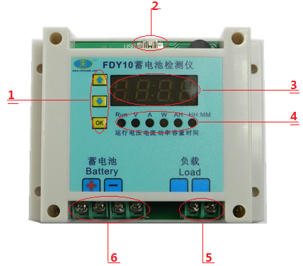
Item |
Introduction |
Item |
Introduction |
|
1 |
Button |
4 |
LED lights |
|
2 |
USB communication interface |
5 |
Load Terminals |
|
3 |
LED digital tube |
6 |
Battery terminals |
4-1 The introduction of FDY10-H/S
|
Feature Name |
Introduction |
|
Automatic identification of battery voltage |
After the automatic identification function is enabled under the setting mode, the battery with the voltage below 15V is identified to the 12V storage battery, while the battery with the voltage above 15V is identified to be the 16V storage battery. What should be noted is that the battery can be identified only under the 2W mode without connection with any power adapter, and is identified completely at the moment after connected. |
|
Final discharging voltage of battery |
The discharge termination voltage of FDY10-H can be set between 0V ~ 60V, and FDY10-S can be set between 0V ~ 20V. The final discharge voltage in factory default is 10.50V, after starting to identify the 12V or 16V battery automatically, the final discharge voltage of the 12V storage battery is 10.50V, the final discharge voltage of the 16V storage battery is 14V, and after the automatic identification function is enabled, the final discharge voltage is automatically set by the machine, which does not support custom setup. |
|
Setting the discharge current of battery |
When the voltage of the battery to be detected is lower, the current can be set between 0.1A and 10A freely; and when the voltage of the battery is more than 10V, the current can be set between 0.4A and 10A freely. The step value is 0.1A under the setting mode, the step value can be set to be 1A by pressing a key rapidly. If a constant resistance function is enabled in the setting mode, the above setting is invalid. |
|
Over-voltage protection function |
FDY10-S:when the voltage of the battery is over 20V, it can’t discharge, and the instrument will be damaged when the voltage over 40V. FDY10-H:when the voltage of the battery over 60V, it can’t discharge, and the instrument will be damaged when the voltage over 80V. |
|
Anti-reverse protection function |
When the battery is connected reversely, a larger current flows through, which may not burn down the instrument in a short time, but long time reverse is not allowed. |
|
Time setting for rapid detection function |
Can be arbitrarily set among 1 ~ 10min. |
|
Start/stop |
|
|
Auto rotate function |
The meter can display voltage, current, power, AH and discharge time successively. |
|
The warning of finish discharge |
|
|
The display for discharge time of battery |
hour (double digits):min (double digits), for example, 02:15 represents 2 hours and 15 minutes. |
4-2 The features of FDY10-H/S
This product is available for an external power supply, which corresponds to a 3W mode, when the voltage of the detected battery is more than 5V, the external power supply is not needed and the power is supplied by the detected battery, which corresponds to a 2W mode. If you need accurate measurement or a lithium battery and other batteries with smaller voltage are measured, the 3W mode can be adopted for measurement, wherein a supporting DC5V power supply of this product needs to be used when the 3W mode is adopted, or, a self-aid 5V~30V power adapter is used to supply power separately.
5.1.1 Wiring schematic diagram
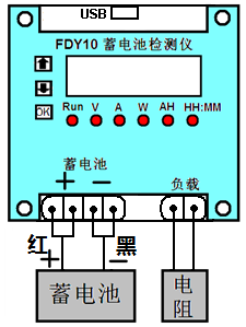
5-1 Schematic diagram of 2W-mode wiring
5.1.2 Wiring Method
Wiring should be performed according to the wiring method as shown in the schematic diagram, the accompanied supporting 1Ω/200W aluminum resistance (For FDY10-H, the number of which can be selected as required, please refer to Supplementary Instructions for details) shall be connected at first during wiring, the screws at the terminal blocks must be tightened, or else, sparks shall appear in the discharge process to burn down the terminal blocks, and then, the test clip is connected onto the storage battery, wherein the positions of the positive and negative electrodes need to be paid attention to.
5.2.1 Wiring schematic diagram
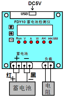
5-2 Schematic diagram of 3W-mode wiring
5.2.2 Wiring Method
Wiring shall be performed according to the wiring method as shown in the schematic diagram, the accompanied supporting 1Ω/200W aluminum resistance (For FDY10-H,the number of which can be selected as required, please refer to Supplementary Instructions for details) shall be connected at first during wiring, the screws at the terminal blocks shall be tightened, or else, sparks shall appear in the discharge process to burn down the terminal blocks. Then connect the DC5V~30V power adapter for the instrument, set the desired parameters, and finally, connect the test battery and pay attention to the positive and negative.
6.1.1 Select the appropriate connection mode based on the measured battery voltage range.
6.1.2 Connecting the battery and the load according to the schematic diagram, pay attention to the positive and negative of the battery when connecting.You should select the number of aluminum resistance according the need.
6.1.3 The LED digital tube will display the voltage of the battery by default when connecting.
6.2.1 Setting the discharge current quickly
The default discharge current of the meter is 10A.
![]()
![]()
![]() If
the discharge
current needs to be changed, press
the
key
to make the current LED indicator light flicker at the position “A”,
at this
moment,press
the key andkey
to realize the rapid cyclic setting among several common
discharge
currents such as 1A, 2A, …, and 10 A, then press
the
“OK”
key
to
confirm
and quit, which is the method for rapid current setting.
If
the discharge
current needs to be changed, press
the
key
to make the current LED indicator light flicker at the position “A”,
at this
moment,press
the key andkey
to realize the rapid cyclic setting among several common
discharge
currents such as 1A, 2A, …, and 10 A, then press
the
“OK”
key
to
confirm
and quit, which is the method for rapid current setting.
If the discharge current needs to be set based on the step value of 0.1A,you should enter the setting mode.
6.2.2 Enter the setting mode
Press the “OK” key for a long time, when the LED indicator light flicker at the positions “V”, it means that you have entered the setting mode. At this point press "OK" button, you can turn to set discharge voltage, discharge current, save and exit, automatic recognition, rapid detection and constant resistance mode. After the setting,you should enter the save interface if you want to save the parameters. The meter will automatically exit the setting interface after saving.If you just want to change the parameters temporarily and don’t want to save them, you can always press "OK" to exit the setting mode.
|
|
Voltage Value |
Current Value |
ES-n |
AU-n |
F-00 |
Cr-n |
|
LED light |
Flickering at “V” |
Flickering at “A” |
No light |
No light |
No light |
No light |
|
Function number |
1 |
2 |
3 |
4 |
5 |
6 |
|
Corresponding Functions |
Setting of final discharge voltage |
Setting of discharge current |
Save and quit |
Identify the battery of 12V/16V automatically |
Rapid detection time (min) |
Setting of constant resistance mode |
6-1 Function Table of Setting Mode
6.2.3 Setting the final discharge voltage of the battery
![]()
![]()
![]()
![]() Function
1:The
final discharge
voltage of the battery is 10.5V, if you want to change it, you need
to enter the setting mode.the
indicator light “V
”flickers
correspondingly, press
the
or key
for
a short time to increase or decrease the final discharge voltage
value of the battery, and press
theorkey
for a long time to change the final discharge voltage value quickly,
the step value is set to be 0.01V when the voltage is smaller than
10V and is set to be 0.1V when the voltage is more than 10V.
Function
1:The
final discharge
voltage of the battery is 10.5V, if you want to change it, you need
to enter the setting mode.the
indicator light “V
”flickers
correspondingly, press
the
or key
for
a short time to increase or decrease the final discharge voltage
value of the battery, and press
theorkey
for a long time to change the final discharge voltage value quickly,
the step value is set to be 0.01V when the voltage is smaller than
10V and is set to be 0.1V when the voltage is more than 10V.
6.2.4 Setting the discharge current accurately
![]()
![]()
![]()
![]() Function
2 is used to set the discharge current of the battery, the indicator
light “A”
flickers correspondingly, press
the
or key
for
a short time to increase or decrease the
discharge
current
value, and press
theor key
for a long time to change the discharge current value quickly, and
accurate regulation is performed by taking 0.1A as the step value
here.
Function
2 is used to set the discharge current of the battery, the indicator
light “A”
flickers correspondingly, press
the
or key
for
a short time to increase or decrease the
discharge
current
value, and press
theor key
for a long time to change the discharge current value quickly, and
accurate regulation is performed by taking 0.1A as the step value
here.
6.2.5 Save and quit
![]()
![]() Function
3 is used to
save
the parameters,
and the default ES-n indicates not
save.
When the parameters are set well and need to save,
press
theorkey
for a short time to switch to the display of “ES-y”, then
press
the “OK”
key
to save the current parameters and quit the setting mode
automatically, and a tweet is sent out after saving, so that the
saved parameters cannot be lost after power interruption. If the
parameters are changed temporarily and in no need of saving,press
the “OK” key for a long time to quit the debug mode.
Function
3 is used to
save
the parameters,
and the default ES-n indicates not
save.
When the parameters are set well and need to save,
press
theorkey
for a short time to switch to the display of “ES-y”, then
press
the “OK”
key
to save the current parameters and quit the setting mode
automatically, and a tweet is sent out after saving, so that the
saved parameters cannot be lost after power interruption. If the
parameters are changed temporarily and in no need of saving,press
the “OK” key for a long time to quit the debug mode.
6.2.6 Automatically identify the battery
![]()
![]() Function
4 “AU-n” is used for identifying
the battery
automatically,
which is off in default. When you need to discharge 12V and 16V
batteries mainly, this
feature can be turned on,press
the or
key
to turn to “AU-y”, then
use
function 3 to
save.
Under the automatic identification mode, the buzzer
sends out one long tweet and one short tweet at the power-on moment
when the 12V storage battery is connected, and sends out one long
tweet and two short tweets at the power-on moment when the 16V
storage battery is connected, what should be noted here is that the
automatic identification is completed only at the moment when the
detector is connected with the battery, and this function is
effective only when the storage battery is connected under the 2W
mode, and the final discharge voltage cannot be changed after the
automatic identification function is enabled.
Function
4 “AU-n” is used for identifying
the battery
automatically,
which is off in default. When you need to discharge 12V and 16V
batteries mainly, this
feature can be turned on,press
the or
key
to turn to “AU-y”, then
use
function 3 to
save.
Under the automatic identification mode, the buzzer
sends out one long tweet and one short tweet at the power-on moment
when the 12V storage battery is connected, and sends out one long
tweet and two short tweets at the power-on moment when the 16V
storage battery is connected, what should be noted here is that the
automatic identification is completed only at the moment when the
detector is connected with the battery, and this function is
effective only when the storage battery is connected under the 2W
mode, and the final discharge voltage cannot be changed after the
automatic identification function is enabled.
6.2.7 The function of rapid detection
![]()
![]() Function
5 is the function
of rapid
detection.
The
default display is the "F-00", indicates the rapid
detection feature is not enabled, this time will be regular full
discharge detection. The rapid detection function is enabled when a
non-zero
value is set, “F-01” to “F-10” correspond to
1-10 min of the discharge time, press
theorkey
to
regulate
the rapid detection time, after the rapid detection time is well set
and saving and quitting operations are performed according to the
function 3,
press
the
“OK”
key
to start rapid detection, the detection time is the set time, and
after the rapid detection is completed, the buzzer will give out an
alarm and the capacity of the battery will be displayed in the LED
nixie tube. (Please refer to Supplementary Instructions for rapid
time setting).
Function
5 is the function
of rapid
detection.
The
default display is the "F-00", indicates the rapid
detection feature is not enabled, this time will be regular full
discharge detection. The rapid detection function is enabled when a
non-zero
value is set, “F-01” to “F-10” correspond to
1-10 min of the discharge time, press
theorkey
to
regulate
the rapid detection time, after the rapid detection time is well set
and saving and quitting operations are performed according to the
function 3,
press
the
“OK”
key
to start rapid detection, the detection time is the set time, and
after the rapid detection is completed, the buzzer will give out an
alarm and the capacity of the battery will be displayed in the LED
nixie tube. (Please refer to Supplementary Instructions for rapid
time setting).
6.2.8 Constant resistance mode
![]()
![]() Function
6 is
the
constant resistance mode, which is off in default. Under the off
condition, the system can regulate PWM automatically according to a
set current value so as to make discharge current equal to the set
value to obtain constant current, press
the
or key
to turn to “Cr-y”, the setting mode is quit after saving,
then the constant resistance mode is started, the constant current
function is disabled automatically, the set current value is invalid,
and the discharge current depends on the voltage of the battery and
an external discharge resistor. (Please refer to Supplementary
Instructions for a specific calculation method).
Function
6 is
the
constant resistance mode, which is off in default. Under the off
condition, the system can regulate PWM automatically according to a
set current value so as to make discharge current equal to the set
value to obtain constant current, press
the
or key
to turn to “Cr-y”, the setting mode is quit after saving,
then the constant resistance mode is started, the constant current
function is disabled automatically, the set current value is invalid,
and the discharge current depends on the voltage of the battery and
an external discharge resistor. (Please refer to Supplementary
Instructions for a specific calculation method).
6.2.9 Run
![]()
![]()
![]() After
the
setting,
press
the
“OK”
key,
the run indicator light “RUN” is on, indicating that the
battery is started to be discharged, after several seconds, the
current can reach the
set value (except for the constant resistance mode).
At
the moment, press
the
key
to switch to different parameter displays.If
you want to display each parameter automatically, you can press the
key for a while until the buzzer
tweet for a while, it means that you have entered the round display
mode.Press
the key again to cancel rotate function.
What
should be noted here is that the ampere-hour of the capacity and time
belong to cumulant.
The flashing state of the decimal point in the LED digital tube
indicates that the AH is being measured,
and the
flicking of the
colon in
the LED digital
tube shows
that the discharge time is in process of cumulating.
After
the
setting,
press
the
“OK”
key,
the run indicator light “RUN” is on, indicating that the
battery is started to be discharged, after several seconds, the
current can reach the
set value (except for the constant resistance mode).
At
the moment, press
the
key
to switch to different parameter displays.If
you want to display each parameter automatically, you can press the
key for a while until the buzzer
tweet for a while, it means that you have entered the round display
mode.Press
the key again to cancel rotate function.
What
should be noted here is that the ampere-hour of the capacity and time
belong to cumulant.
The flashing state of the decimal point in the LED digital tube
indicates that the AH is being measured,
and the
flicking of the
colon in
the LED digital
tube shows
that the discharge time is in process of cumulating.
6.2.10 View the test results
![]() Along
with discharge, the voltage of the battery decreases constantly.
At the
conventional detection of the full discharge,
when the voltage is decreased to the set final discharge voltage, the
discharge is stopped automatically.
Whereas,
if the rapid detection mode is started, discharge will be stopped
after the set time is up and the estimated capacity of the battery is
calculated automatically, meanwhile, two prompt manners including
flickering of the LED nixie tube and alarming of the buzzer will
prompt you to check measurement results, and at the moment, you shall
press any key to stop the alarming of the buzzer at first and then
press the key
to check each measurement result in sequence.
Along
with discharge, the voltage of the battery decreases constantly.
At the
conventional detection of the full discharge,
when the voltage is decreased to the set final discharge voltage, the
discharge is stopped automatically.
Whereas,
if the rapid detection mode is started, discharge will be stopped
after the set time is up and the estimated capacity of the battery is
calculated automatically, meanwhile, two prompt manners including
flickering of the LED nixie tube and alarming of the buzzer will
prompt you to check measurement results, and at the moment, you shall
press any key to stop the alarming of the buzzer at first and then
press the key
to check each measurement result in sequence.
6.2.11 Clear
![]()
![]() When
the measurement results are checked, set to the capacity “AH”
display mode and press the key
for a long time to carry out zero clearing on the capacity, and set
to a time “HH:MM” display mode and press the key for a
long time to carry out zero clearing on the time, and the capacity
and the time may undergo zero clearing automatically after power
interruption.
When
the measurement results are checked, set to the capacity “AH”
display mode and press the key
for a long time to carry out zero clearing on the capacity, and set
to a time “HH:MM” display mode and press the key for a
long time to carry out zero clearing on the time, and the capacity
and the time may undergo zero clearing automatically after power
interruption.
7.1 The rapid detection function is a unique enhancement function of our product and can be used without discharging the battery fully before a test, the battery does not need to be discharged completely after the test, and when the remaining capacity of the battery is 25-75%, the numerical measurement is more accurate. It is a necessary condition for enhancing the measurement accuracy by setting the discharge current and discharge time reasonably, the discharge curves varies among different batteries, and the experience accumulated through constant trials is the best path to setting, and we will illustrate a general setting method as below:
The final discharge voltage shall be set reasonably according to battery specifications.
The set maximal value of the current is 1C rate generally, for example, the maximal discharge current of a 3AH battery is 3A, the detection time may be 1 min at the moment, the measurement results will be more accurate if smaller discharge current and longer measurement time are set, and an experience table is listed below for reference only:
|
Battery Type |
Voltage: 12V Capacity: 12AH |
Voltage: 3.7V Capacity:2.5AH |
||||
|
Final discharge voltage |
10.5V |
10.5V |
10.5V |
3.0V |
3.0V |
3.0V |
|
Discharge Current |
10A |
5A |
3A |
2A |
1A |
0.6A |
|
Rapid detection time |
1 min |
2 min |
3 min |
1 min |
2 min |
3 min |
If there is a larger deviation between the capacity obtained through rapid detection and your anticipated capacity, please charge the battery fully for a full discharge test. Or, you may try different
rapid detection currents and time to find out an experience value closest to the correct capacity, which may provide experience for you to test other batteries of the same type later.
7.2 Constant resistance function is used to cancel the automatic constant current for PWM so as to discharge the battery directly through the external discharge resistor, this mode is unavailable for constant current yet does not influence the accuracy of the metered ampere-hour, therefore, this function can be enabled if necessary, and a current calculation method is as follows:
specific current=battery voltage/power resistance (with the value of 1Ω or others)
7.3 If the voltage of the detected battery is smaller than 10V, the maximal discharge current is not going to reach 10A, and the calculation method of the discharge current is as follows:
maximal current=battery voltage/power resistance (with the value of 1Ω),
for example, the maximal current corresponding to the battery with the voltage being 3.7V is only 3.7A , if the discharge current needs to be increased, the following two methods can be adopted:
Reducing the external power resistor, this method should be noted that when measuring the battery with higher voltage , the resistance is ought to be switched to 1Ω, or may not be tested;
2.In case of using the resistor of 1Ω, a magnetic ring inductor of about 100uH shall be connected with the resistor in parallel, wherein any 100uH magnetic ring inductor with the maximal current reaching 10A can be selected.
7.4 The matching relationship of battery voltage and power resistor of FDY10-H.
|
Voltage Range of Battery |
Number of Resistor |
Resistance value and Power |
|
0~15V |
1 |
1Ω 200W |
|
15V~30V |
2 |
2Ω 400W |
|
30V~45V |
3 |
3Ω 600W |
|
45V~60V |
4 |
4Ω 800W |
1、The resistors are connected in series and can be increased or decreased according to actual demand.
2、The final discharge voltages of battery packs with different voltages are different and need to be set by oneself, and taking the serial connection of four 12V lead-acid batteries as an example, the final discharge voltage is 4*10.5V=42V.
1、Please reverse positive and negative electrodes when the detector is connected with a storage battery.
2、Please prohibit outrange usage.
3、Please place the detector at a safe place to prevent scalding since the power resistors have higher temperature during discharging at full load.
9.Warranty
and service
Thank you for purchasing our
products. To maximize the use of
the new product features, we
recommend that you take the following steps:
1 Read safe and
efficient use
instruction.
2 Read the
warranty terms and conditions.
We warrants to the original purchaser that its product and the component parts thereof will be free from defects in workmanship and materials for a period of one year from the data of purchase.
We will repair or replace, at its option, defective product or component parts. Returned product must be accompanied by proof of the purchase date.
Exclusions: This warranty does not apply in the event of misuse or abuse of product or as a result of unauthorized alternations or reapers. It is void if the serial number is alternated, defaced or removed.
304 OPERATING POLICY & PROCEDURE SUBJECT STAKEHOLDER INPUT
5 STAGE WASH CHEMICAL CONTROLLER OPERATING PROCEDURE ATTACHMENTS 1
510 REVISED 92011 CREDIT AND DEBT MANAGEMENT OPERATING STANDARDS
Tags: battery tester, of battery, manual, battery, december, zhengzhou, fdy10hs, tester, operating
- L GPS FACTSHEET PENSIONS TAXATION ANNUAL ALLOWANCE HM
- BUSH KINDER EXTREME WEATHER POLICY NQS QUALITY AREA 2
- REVIEWING THE VOUCHER TO DETERMINE WHY IT HAS NOT
- LEY 29493 DE IMPACTO AMBIENTAL PRESENTACION LA SUBSECRETARÍA
- …………… İLÇE MİLLİ EĞİTİM MÜDÜRLÜĞÜ ………… LİSESİ DOKÜMAN NO
- AN EBSD STUDY OF THE DAMAGE TO ZIRCON CRYSTALS
- 1951 BVA SPEECH BOSTON MASS I TOLD YOU IN
- JURNAL MOTIF WARGA KARESIDENAN SURAKARTA BERKONTRIBUSI DALAM
- ADDRESS BY IRINA BOKOVA DIRECTORGENERAL OF UNESCO FOR THE
- DOSIER DE PRENSA JUBILEOS DE MONTELLANO DEL 2 AL
- TALLERES DEPORTIVOS MUNICIPALES – ACTIVIDADES DEPORTIVAS PARA NIÑOS Y
- UNIVERSITAS INDRAPRASTA PGRI JALAN NANGKA NO58 TANJUNG BARAT JAGAKARTA
- DECLARATION FOR NEW POLITICAL PARTY WE THE UNDERSIGNED QUALIFIED
- 13 CORPORATIZING THE UNCONSCIOUS MEMES NEUROMARKETING AND CHRISTOPHER NOLANS
- SYMPOSIUMMHEWSSDDOC 21 P 2 WORLD METEOROLOGICAL ORGANIZATION TTM&EDOC 11
- ESPECIFICACION DE REQUERIMIENTOS SOFTWARE [NOMBRE DEL PROYECTO] PREFACIO ESTE
- ALUMNOS CRONOGRAMA DE PROCESOS ESCOLARES EVALUACION EXTRAORDINARIA ESPECIAL INSCRIPCIÓN
- 4 BÉRLETI AJÁNLAT SZOCIÁLIS LAKÁSRA AZ IGÉNYLŐ HÁZASTÁRS
- MODELO DE PROYECTO PERSONAL PARA LA REALIZACIÓN DE ESTANCIAS
- MODELLO GAMMA SCHEMA OFFERTA ECONOMICA OGGETTO PROCEDURA
- MYSŁOWICE DN 30112015R SZP2NZ42401515 DOTYCZY KONKURSU OFERT NA UDZIELANIE
- MEMORIA RTVA 2015 ÍNDICE MEMORIA RTVA 2015 1 INTRODUCCIÓN…………………………………………………………………4
- NZQA EXPIRING UNIT STANDARD 11761 VERSION 5 PAGE 3
- GROUPE HOSPITALIER HENRI MONDOR SITE ALBERT CHENEVIER HENRI
- ANKARA MİKRO ÖLÇEĞİNDE İNTERNET KAFELER KULLANIM BİÇİMLERİ MUTLU BINARK
- TIPS FOR COOKING WITH KIDS ENJOYING FOOD WITH STUDENTS
- PLAZA DE JUAN XXIII 30008 MURCIA TELÉFONO 012
- CHAPTER 2 THE BASICS OF SUPPLY AND DEMAND CHAPTER
- БАЗА ПУБЛИКАЦИЙ И ПЕРЕЧЕНЬ ИХ БИБЛИОГРАФИЧЕСКИХ ЗАПИСЕЙ (КАФЕДРА ТЭАИРЭО)
- CE TREBUIE SĂ FACĂ UN RECENZOR ? RECENZORUL TREBUIE
 S UBMISSION OF THE EUROPEAN NETWORK OF (EX) USERS
 F ACTSHEET M THERE ARE 2 MODELS OF DISABILITY
 UNCLASSIFIED NATIONAL SECURITY FRAMEWORK REF NSF 12 CATEGORISATION FUNCTION
 LIBRO PRIMERO TITULO I “DE LA FEDERACIÓN DE ESTUDIANTES
 2.%20DAFTAR%20RIWAYAT%20HIDUP
 WWWMONOGRAFIASCOM ARQUITECTURA DE LOS SISTEMAS DE BASES DE
 ROMÂNIA JUDEŢUL CONSTANŢA CONSILIUL JUDEŢEAN PREŞEDINTE DISPOZIŢIA NR 44522092021
UNIVERSIDAD DA CORUÑA BASES DOS PREMIOS DE INVESTIGACIÓN
OZNAKOWANE SZLAKI ROWEROWE WOJ ZACHODNIOPOMORSKIEGO ZNAJDUJĄCE SIĘ W REJESTRZE
 MACROPROCESO MISIONAL SECRETARÍA DE EDUCACIÓN PROCESO GESTIÓN DE EDUCACIÓN
 POWERPLUSWATERMARKOBJECT1298677998 FACTSHEET TAXATION OF HUMANITARIAN ASSISTANCE IS HUMANITARIAN ASSISTANCE
 Taiwan roc Standard Certificate of Death Registration no( Dept
 ESPECIFÍCAR EN SOLICITUD LICENCIA– JUGADORA – ENTRENADORA – DELEGADOA
 MANAGUA NICARAGUA 5 DE OCTUBRE DEL 2012 SEÑORASES
 LEGAL LAND LOCATION ERROR REFERENCE SOURCE NOT FOUND THIRD
ORDINANCE 174 ORDINANCE NO 174 AMENDING SECTION 1102
2017 MARY GONZALES LUNDY AWARD IN HONOR OF MARY
 6 CONECTOR RECTO UNIVERSIDAD DE SONORA REGISTRO DE PROYECTO
LITERATURA INFANTIL I JUVENIL REVISTA DIGITAL CORNABOU (22072010) 0881
VGP CORPORATE GOVERNANCE REPORT (FIRST 6 MONTHS OF 2018)
