OPERATING NOTES – HANDHELD RADIOS (COURTESY OF JIM FRASER
SEARCH AND RESCUE MODEL OPERATING PLAN A GUIDE1 THE OPERATING COMMITTEE OF UNITED STATES POWER SQUADRONS
112 REVISED 92011 CREDIT AND DEBT MANAGEMENT OPERATING STANDARDS
12 STEPS TO TECH HOST USING MAC OPERATING SYSTEM
20 MULTIAGENCY RISK ASSESSMENT CONFERENCING (MARAC) OPERATING PROTOCOL MULTIAGENCY
2623A WIS JI‑CRIMINAL 2623A 2623A OPERATING WHILE SUSPENDED CRIMINAL
ICOM Handset User Guide
Operating Notes – Handheld Radios
(Courtesy of Jim Fraser, Kintail MRT) AUG. 2010
ICOM IC-F31GS or GT (your MRCofS issue radio)
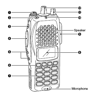
Controls
Diagram: Icom.
Rotary Switches
The smaller rotary switch (11) on the top of the radio turns the radio on and sets the receiver audio volume required. Clockwise to switch on and fully clockwise for full volume.
The larger central rotary switch (12) numbered 1-16 has pre-set channel functions. Only a few are in use : 1 - Channel 62A - Calling; 2 - Channel 24A - Ground-to-air(winch)
3 - Channel 531 - SARDA; 4 - Channel 644 - Ochils TWC
 16 -
Scan (same as button P0). Remainder are Ch 62A
16 -
Scan (same as button P0). Remainder are Ch 62A
The selected channel becomes active when the radio is switched on.
The Red button (2) locks the handset stopping any function button operating. When this lock is on, a small key is shown on the display.
PRESS AND HOLD to lock.
PRESS AND HOLD to unlock.
NB - the handset will remain locked in this configuration after switching off and back on.
Side Buttons
The top button (3) on the left side is the open squelch button (sometimes called monitor) and pressing this removes the squelch function from the received signal. During normal operation, only good strong signals are heard. When this button is pressed, all signals, including background noise, can be heard. This is sometimes required to hear incoming signals that are weak. It is rarely required in mountainous country where all distant signals tend to be obstructed by high ground.
PRESS AND HOLD to open squelch. RELEASE to close.
The large second button down (4) is the Press To Talk (Transmit) button. This is not used in normal operation because the equivalent button on the microphone is used.
The bottom two buttons (5) are channel up and channel down.
SHORT PRESS to change one channel.
PRESS AND HOLD to scroll through channels.
The Channel shown on the display (8) is the active channel and transmission and reception are on this channel. These buttons and the 16-way selector switch over-ride each other: the last control used selects the active channel and over-rides the previous selection using either of the controls. (Selector switch has priority as switch on.)
Function Buttons - P0 to P3 (6)
P0. Start/Stop Scanning.
PRESS ONCE to start the Scan function.
PRESS again to stop the scan function.
When started, the set cycles through the channels in the scan group. When a transmission is detected, the channel is shown on the display (8) and the channel is held for a few seconds to enable you to reply on the same channel.
P1. Priority Channel.
SHORT PRESS: selects the Priority Channel. When the Priority Channel is selected an “A” is shown on the display (8).
PRESS AND HOLD: sets the displayed channel as the Priority Channel. Channel 62A is set as the Priority Channel during normal operations. The radio switches to the Priority Channel when you interrupt scanning.
P2. Home Channel.
PRESS AND HOLD: sets the displayed channel as the Home Channel. Channel 644 is set as the Home Channel. A small house icon is shown on the display (8), when the Home Channel is selected. The Home Channel is always in the scan group.
P3. Scan on/off.
SHORT PRESS: adds or deletes the selected channel in the scan group. A flag icon is shown on the display (8) when the selected channel is in the scan group. The normal scan group for Ochils is 62A and 644. Channel 24A (“Winch”) can be added for large operations.
Microphone (not shown: attached at (9))
The Grey Button is the Press To Talk (Transmit) button. PRESS it when you want to transmit a message and RELEASE it after you are finished. Make a habit of a very short pause after pressing the button before you speak and a pause again after you finish speaking before releasing the button. This overcomes the extremely common habit of cutting off both ends of your speech.
The distance between your mouth and the microphone should be the thickness of a fist.
Be sure that you protect Press To Talk button from accidentally being pressed: accidental transmissions prevent the channel from being used by others.
Channels
The Ochils Team Working Channel (TWC) is 644. Neighbouring teams are working on the following channels.
Tayside 243, Moffat 244, Killin 623, Tweed Valley 624, Borders 634, Lomond 852.
Team names appear in the second line of the display.
CAUTION
Our transmissions are not digitised, encrypted or scrambled. All channels with 3-digit numbers have 12.5kHz spacing and are 6.25kHz from the standard marine band channels. This means that none of our transmissions on these channels can be heard using the standard set-up on marine band radios and this gives an additional degree of privacy on these channels. However, ordinary scanning receivers and programmable receivers can still be used to listen to our transmissions.
The UK Land SAR Standard Operating Procedure defines channel management for Land SAR parties, vehicles and helicopters.
The Standard Operating Procedure for hill parties is for each person to listen on one channel only. The party leader should allocate channels. Often only 644 and 62A are necessary. If several aircraft and several teams are active in the district then it becomes more likely that aircraft will use 24A.
Instructions for listening on other channels may be given by Communications Officers during large operations. This may also be necessary when relay stations, repeaters or rebroadcast systems are used.
Scan Function
The scan function exists to allow a single radio to monitor more than one radio channel. This is necessary if there are insufficient radios at a location for each channel to be monitored by at least one radio. It is better to organise for listening on one channel only.
The UK Land SAR Standard Operating Procedure allows for the use of scanning. Scanning with a handheld radio in a hill party is correct when there is only one radio in that hill party.
Scanning has the disadvantage, particularly in the conditions that exist on the hill, that a reply can easily be made on the wrong channel. This may lead to confusion on two channels and amongst several radio users, a result that can easily be avoided by the proper procedure of assigning each channel to a different radio.
The scan function is not there so that every nosey foot-soldier can hear everything that is going on. That is the job of the Team Leader or other Rescue Co-ordinator.
NOTE
A shortage of memory assigned to some features of the radio means that during scanning, a line of ÿ characters appear in the second line of the display. This is normal and meaningless and it can be ignored.
Priority Channel
If you transmit when the radio is scanning then the transmission is on the Priority Channel. This channel can be selected by the user. The letter A is shown on the display when the priority channel is selected. Normally, the priority channel should be 62A
During some operations, it may be necessary or desirable to select another Priority Channel. Do not do this without a good reason.
Home Channel
The Home Channel is always part of the scan group. The correct Home Channel is 644. This ensures that the user always hears messages from other teams, aircraft and emergency messages from any Land SAR station. This channel can be selected by the user. A house symbol is shown on the display when the home channel is selected.
Do not change the Home Channel.
Scan Delay Time
During scanning, if the radio receives a transmission on one of the channels in the scan group then it stops scanning and the user can hear the message transmitted on that channel. At the end of the transmission, the radio remains on the same channel for about 2 or 3 seconds. If you transmit during this period then you will be able to reply on the same channel without making any adjustments to your radio.
Note that all. transmissions started after the Scan Delay Time has lapsed will be on the Priority Channel 62A.
If a message is for you then make ready to transmit a reply. Be ready to transmit as soon as you hear the word OVER. This will enable you to make use of the Scan Delay Time to reply on the correct channel.
Identity
Always identify your transmissions with your call sign.
The radios are issued to individuals and are traceable by the User ID No and serial number. Your name is recorded against each of these numbers and held by the government. Transmissions are identifiable by User ID. Remember that they should only be used for Mountain Rescue purposes and any misuse may be seen as a radio licence violation by Ofcom.
This does not mean that you cannot take your radio on to the hill at other times. Several rescues have been done in Scotland when members of one or more teams have been available on the hill and able to co-ordinate their efforts or to direct SAR aircraft to an incident using their radios.
Battery Care
You have been issued with 2 rechargeable radio batteries and an Icom BC-119N charger with a mains power supply. A spacer in the charger can be fitted in different positions to allow charging of the battery with or without the radio. Normally, one battery is a Nickel Metal Hydride (Ni-MH) type and the other is a Lithium ion (Li-ion) type. The Lithium ion battery has a better tolerance to cold weather and is the primary choice for winter use. Ensure that both batteries are charged and that they are both carried when attending call outs or training. Take care to prevent shorting of the terminals when the spare battery in your rucksack. A cheap and easy way to do this is to wrap it in plastic bag.
To conserve battery energy, plan your messages and keep them short. Avoid scanning.
The Charge Indicator (Source: Icom)
• Lights orange while charging.
• Lights green when rapid charging is completed.
- But it is still charging in trickle charge mode when charging a Ni-MH battery.
• Flashes red when the protection circuit is activated.
- Check the power source (voltage) or re-connect the power plug.
- The battery temperature is outside of the charging range (Ni-MH battery only).
Ni-MH Battery Charging (Source: Icom)
These work best when fully charged before use and then run flat before recharging: doing this will help improve battery life. The battery charger rapidly charges a battery pack to a specified level, not a completed level, to prevent over-charging. Leave the Ni-MH battery pack in the charger for a few more hours (up to 15 hours; depending on battery condition) after the LED indicator turns green, to charge the battery completely.
Lithium Ion Battery Charging (Source: Icom)
The Lithium Ion battery should be fully charged before use and can be charged without being fully discharged. It is not necessary to completely discharge and charge Li-Ion batteries to prolong the battery life. This battery type should not be left in the charger for prolonged periods when the fully-charged indicator is on: remove the item from the charger as soon as possible after the indicator turns to green.
Safety
Batteries can overheat, catch fire, vent toxic gases or explode if damaged or incorrectly charged. Observe the correct charging instructions. Examine a battery for damage before charging it, fitting it to a radio or storing it in your rucksack.
Lithium batteries bring additional hazards. Refer to the section on Faulty Equipment for further information.
Antenna Use
Two types of antenna have been issued. One is a short wound type of antenna for fitting directly to the radio that is useful for short ranges and when using the radio on your person and separate from your rucksack. It is screwed into the antenna connector (1) on top of the radio. The antenna works correctly only when it is orientated vertically.
The other antenna is a half wave dipole. This is an extremely effective antenna that works well out to the extremes of range of these radios. It is connected to the radio using an adapter that screws into the antenna connector (1) on top of the radio and an extension lead that is part of the antenna assembly. It is intended for mounting on your rucksack. One or more loops of shock-cord tied to the centre-bracket of the antenna may make it easier to secure it firmly to your rucksack.
Ensure that your antenna adapter is attached to your radio case by its lanyard so that it does not get lost. If you fit a new adapter then the outer collar may be a tight fit (you may need to open the collar a little using a pair of small pliers).
The dipole rucksack antenna works correctly only when it is mounted vertically and the section marked “E” is downwards. Mark the lower (E) section of your dipole antenna with a piece of green tape so that you remember to point it towards the grass!
All antennae work correctly only when they are not obstructed. Stand so that your antenna is not obstructed in the direction of the station that you are listening to or calling.
Faulty Equipment
Always report faulty equipment to the Radio Officer. A few spares of radio accessories are kept locally. Replacement equipment can normally be organised within a few days.
These radios are very reliable and durable. However, please try to avoid driving over them, dropping them in rivers or dropping them down cliffs. The most likely faults when out on the hill are in the accessories: antenna, microphone and battery.
Antenna
You have been issued with 2 types of antenna. Always take both on callouts and training. If the antenna is faulty then change to the other type.
Microphone
Broken wires in the microphone lead, a faulty PTT microswitch or water ingress are possible faults. If a fault occurs, remove the microphone connector and use the PTT switch and microphone on the body of the radio.
Microphones affected by water ingress normally recover after drying out in normal indoor conditions.
Battery Low
The radio will change to transmitting on Low power long before you notice any difference. When receiving, the word ‘Low’ appears on the display and the battery indicator changes to one or two bars. Change to your spare battery. Pool spare batteries amongst the hill party.
Battery Safety, Lithium-ion
Lithium-ion batteries are reliable and safe when used correctly. Overheating, due to fire, incorrect charging or short-circuit may result in explosion. Hydrogen Fluoride gas may be released. A dangerous reaction may continue even after the cause of heating is removed. Explosions and fires can occur in a series. Extinguishing is not possible with normal methods. A toxic or explosive hazard may also occur if the Lithium ion battery case becomes cracked and water ingress occurs.
If a crack or other deformation is noticed in the case, or serious overheating has occurred, then remove the battery and abandon it. The suspect battery must not be taken onboard any aircraft. ‘Mark’ the location of an abandoned battery with your GPS. Notify the Radio Officer so that safe disposal can be arranged.
Repair Contractor
For the period 2010 to 2015, the MRCofS radio contractor is Radio Telecom Services Ltd (RTS) of Livingston. The team’s relationship with RTS is handled by the Radio Officer and the Treasurer. Other team members do not need to contact the contractor unless directed by the Radio Officer.
Page
304 OPERATING POLICY & PROCEDURE SUBJECT STAKEHOLDER INPUT
5 STAGE WASH CHEMICAL CONTROLLER OPERATING PROCEDURE ATTACHMENTS 1
510 REVISED 92011 CREDIT AND DEBT MANAGEMENT OPERATING STANDARDS
Tags: (courtesy of, notes, radios, fraser, (courtesy, operating, handheld
- 10 2014 GADA 25 NOVEMBRĪ NOTEIKUMI NR 717 RĪGĀ
- MACROPROCESO GESTIÓN ADMINISTRATIVA Y FINANCIERA CÓDIGO UFT12004063 VERSIÓN 50
- LA ESCULTURA COMO SIGNO “UNA BUENA ESCULTURA DEBE TRATARSE
- ACTIVIDAD 2 UNIDAD 1 NOMBRE FECHA APELLIDOS
- PALABRAS TÓNICAS Y PALABRAS ÁTONAS TODAS LAS PALABRAS POSEEN
- MINISTERSTVO OBRANY ODBOR KOMUNIKACE A PROPAGACE V PRAZE DNE
- CURSO PROGRAMACIÓN ESTRUCTURADA TRIMESTRE 20I PROF G KHATCHATOUROV MANDAR
- ARICA DIECISÉIS DE MAYO DE DOS MIL CINCO VISTO
- DIVISIÓN GESTION HUMANA INSPECCIÓN TÉCNICA FORMULARIO DE RECLAMO POR
- MITTHÖGSKOLAN INSTITUTIONEN FÖR INFORMATIONSTEKNOLOGI OCH MEDIER AVDELNINGEN FÖR INFORMATIONS
- SPIS TREŚCI SPIS TABEL 2 SPIS MAP 5 1
- 66 BAB IV PENERAPAN METODE DEMONSTRASI PADA MATA PELAJARAN
- NORMATIVA IVAJGENERALITAT JOVE SOBRE CURSOS DE FORMACIÓN DE MONITORES
- ASPERGERIO SINDROMĄ TURINTIS VAIKAS PAGAL TONNY ATTWOOD KNYGĄ ASPERGERIO
- ADALBERTO NAVARRO SÁNCHEZ CONDECORACIÓN JOSÉ MARÍA VIGIL DECRETO 7051
- TALLER EN CLASES EJERCICIO CLÍNICA CREA EN LA BASE
- NÁVRH OBJEDNÁVKA ČÍSLO 8717849620218407 ČESKÁ REPUBLIKA – MINISTERSTVO
- AQUÍ ESTOY EN EL AEROPUERTO DE TENERIFE NORTE RUMBO
- 13 AKTEA 20121213 HAMAHIRUGARREN AKTEA ZUZENDARITZA BATZORDEA ORGANOA
- HISTORIA I EPISTEMOLOGIA DE LA PSICOLOGIA 1 HISTÒRIA
- PROPOSED REGULATORY LANGUAGE COMMITTEE II –ACGNATIONAL SMART GRANT ISSUES
- AMIDILA – ACADEMIC MOBILITY AND INCLUSIVE DEVELOPMENT IN LATINA
- DIRECCION DE ENSEÑANZA ACTUALIZADO 25112021 ESCUELA DE GUERRA DEL
- INSPECTION OF FURTHER EDUCATION COLLEGES WITH RESIDENTIAL PROVISION FOR
- RÁTZ LÁSZLÓ VÁNDORGYŰLÉS VESZPRÉM 2009 JÚLIUS 710 NAGYBALÓ ANDRÁS
- GLOSSARY OF TERMS FIELD EDUCATIONFIELD PRACTICUM INTERNSHIP – THIS
- KULTURNOUMJETNIČKI AMATERIZAM UPUTE ZA NAMJENSKO KORIŠTENJE SREDSTAVA U 2021
- “EL VOCABULARIO DE LA ARGUMENTACIÓN” DRA PATRICIA NIGRO 1
- COMPANY INFORMATION COMPANY NAME BIOVELA GROUP ADDRESS DUKSTŲ KM
- PRIMER ENCUENTRO NACIONAL DE REVISTAS LITERARIAS HOMENAJE POR EL
 ANMÄLNINGSBLANKETT FÖR STUDIECIRKEL OCH ANNAN FOLKBILDNINGSVERKSAMHET PÅ WWWABFMEDIALABSE ÄMNESTUDIECIRKELNS
ALLGEMEINE ARBEITSREGELN FÜR LABORATORIEN • SICHERHEITSVORKEHRUNGEN DES LABORBEREICHES UND
WELD COUNTY SCHOOL DISTRICT RE5J EMPLOYEE FIRST REPORT OF
NA OSNOVU ČLANA 23 ZAKONA O NAMJEŠTENICIMA U ORGANIMA
 DOCUMENTACIÓN LICITACIÓN PÚBLICA CONCURSO INVITACIÓN ADJUDICACIÓN DIRECTA ADMÓN DIRECTA
 EN ESTA AGENDA ENCONTRARÁS INFORMACIÓN SOBRE LA CULTURA ESPAÑOLA
 DESIGNACIÓN DE ESPECIALISTA EN FÍSICA DE LA RADIOTERAPIA Y
HOW TO CALCULATE STATISTICS FOR SLOPE RATIO ASSAYS THE
V22 112011 RICHIESTA DI (RI) CERTIFICAZIONE LA
 INFORME SEGUNDO SEMESTRE DE 2015 COOP57 ANDALUCÍA EN ESTE
 13 EL AFECTO QUE TUS HIJOS NECESITAN
 RESUMEN A MODO DE CUESTIONARIO CAPÍTULO 3 MEDICIÓN DE
 THOSE WITH KEEN UNDERSTANDING OF THEIR STRENGTHS AND NEEDS
 STUDENT ACTIVITY FUNDS POLICIES AND PROCEDURES MANUAL O’FALLON COMMUNITY
JOANNA CHOLEWA SARA MOROZ UNIWERSYTET W BIAŁYMSTOKU CONCEPTUALISATION DES
CERTIFICATE OF NATIONALITY OF CORPORATION I HEREBY CERTIFY THAT
 SOURCES FOR “REASONS WHY SCOTS ENLISTED TO FIGHT IN
TREATMENT OF CONTACT LENS COMPLICATIONS COPE 11634 CL SUSAN
 APIE ŠĮ KLAUSIMYNĄ JO NAUDĄ JUMS IR JŪSŲ TEISES
POROČILO O POLLETNIH REZULTATIH IN OPRAVLJENI REORGANIZACIJI V DRUŽBI
