ELECTROTECH TOOLBOX REINFORCEMENT ACTIVITY PARALLEL MEASUREMENT STEP 1
29 6118853 IEC2001 INTERNATIONAL ELECTROTECHNICAL COMMISSION PRINTED BOARD3 Page International Electrotechnical Commission System for Certification to
ELECTROTECH TOOLBOX REINFORCEMENT ACTIVITY PARALLEL MEASUREMENT STEP 1
ELECTROTECHNICAL SERVICES (ELECTRICAL INSTALLATION – BUILDING AND STRUCTURES) LEVEL
EXTRAIT BREVET DE TECHNICIEN SUPERIEUR ELECTROTECHNIQUE SESSION 2012 EPREUVE
LOT EP TBTS 300W ELECTROTECHNIQUE & ELECTRONIQUE DE
Steps in processing a refund
Electrotech Toolbox Reinforcement Activity

Parallel measurement
Step 1
Access the following equipment:
12 volt power source
1 x 12Ω, 2 x 4Ω resistors
connecting wires
multimeter (or individual ammeter, voltmeter and ohmmeter).
Or
A circuit board for training purposes containing the above components, a suitable power source and meters.
Step 2
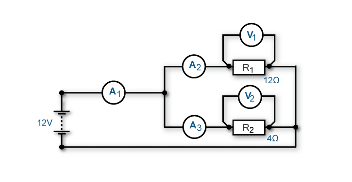
Connect up the circuit shown below.
Note: If you are having any difficulty or are unsure how to connect this circuit, see your trainer for assistance and advice.
Step 3
Set the power source to 12V and turn on. Measure the voltage drop at V1 and V2 and the current flow at A1, A2 and A3. Turn off the power source and write your measured values in the following table.
|
|
Measured value |
Predicted value |
Difference between measured and predicted values |
|
Voltage at V1
|
|
|
|
|
Voltage at V2
|
|
|
|
|
Current through A1
|
|
|
|
|
Current through A2
|
|
|
|
|
Current through A3
|
|
|
|
Step 4
Using the appropriate formula, calculate the predicted values you have measured. Place these values in the table above.
Calculate the difference between measured and predicted values and place in table.
Note: In the following area, show the formula you have used and your calculations.
Briefly explain possible reasons for a difference between measured and predicted values.
|
|
|
|
|
|
|
|
Step 5
Change your circuit to reflect the resistance values shown below.

Step 6
Set the power source to 12V and turn
on. Measure the voltage drop at V1, V2 and V3 and the current flow at
A1, A2, A3 and A4. Turn off the power source and write your measured
values in the following table.
|
|
Measured value |
Predicted value |
Difference between measured and predicted values |
|
Voltage at V1
|
|
|
|
|
Voltage at V2
|
|
|
|
|
Voltage at V3
|
|
|
|
|
Current through A1
|
|
|
|
|
Current through A2
|
|
|
|
|
Current through A3
|
|
|
|
|
Current through A4
|
|
|
|
Step 7
Using the appropriate formula, calculate the predicted values you have measured. Place these values in the table above.
Calculate the difference between measured and predicted values and place in table.
Note: In the following area, show the formula you have used and your calculations.
Briefly explain possible reasons for a difference between measured and predicted values.
|
|
|
|
|
|
|
|
|
|
Step 8
Answer the following questions related to this activity.
What did you notice about the current flow through A1 in relation to the flow through the parallel branch?
|
|
|
|
|
|
What did you notice about the voltage across the resistors in the parallel branch?
|
|
|
|
|
|
What did you notice about the total current flow when an additional resistor was added to the parallel branch (eg step 5)?
|
|
|
|
|
|
|
|
|
|
Step 9
Present your completed task sheet to your trainer for feedback.
Note: This completed task sheet can be saved as evidence of work completed.

UEENEEE004B Solve problems in multiple path DC circuits Parallel measurement - reinforcement
©
Commonwealth of Australia 2009 | Licensed
under AEShareNet – S Licence Disclaimer
and copyright Page
QUESTIONNAIRE ELECTROTECHNIQUE CHAPITRE N°10 EPSIC PROMOTION 2006 CHAPITRE 10
Tags: activity parallel, electrotech, toolbox, parallel, reinforcement, activity, measurement
- COCKTAIL… 35 PER HEAD HOT… MINI SAMOSA WITH
- CRITERIOS DE SELECCIÓN DE TIRO PARA PARTICIPAR EN LOS
- HORARIO DE REFERENCIA MÉXICO ANTENA 3 INTERNACIONAL DOMINGO 09052021
- VIŠEJEZIČNI MEDIJI TRI GODINE POSLE PRIVATIZACIJE ISTRAŽIVANJE EFEKATA
- VZÁJEMNÝ KONTAKT DÍTĚTE A MATKY POSILUJE ZDRAVÍ – MGR
- ZÁKLADNÁ ŠKOLA SLOBODY 1 KOŠICE ŠKOLSKÝ KLUB DETÍ V
- GUÍA 1° AÑO MEDIO”EVOLUCIÓN” NOMBRE GUÍA N° 3 FECHA
- ANEXO XIII REGISTRO DE DEVOLUÇÃO DE TALIDOMIDA POR DESVIO
- FORENSIC SCIENCE FUNDAMENTALS & INVESTIGATIONS CHAPTER 6 ACTIVITY HANDOUT
- JIM THE FOLLOWING IS REQUIRED IMPROVE SERVER RESPONSE TIME
- SPREMNI DOPIS – 2 DEL – PODATKI O IZVEDBI
- ESQUEMA COMPARATIU DE LES CONSTITUCIONS ESPANYOLES DEL S XIX
- ОБРАЗАЦ Ц13 РЕПУБЛИКА СРБИЈА ЗАКОН О ЗВАНИЧНОЈ СТАТИСТИЦИ „СЛУЖБЕНИ
- COMPLETE THIS FORM AS PART OF THE REGISTRATION PROCESS
- ECOVAST EUROPEAN COUNCIL FOR THE VILLAGE AND SMALL
- INDICE PARTE PRIMERA ESTUDIO ESPECIFICO DEL CONTEXTO HISTÓRICO
- M EJRUP GYMNASTIK & UNGDOMSFORENING FODBOLDAFDELINGEN W WWMEJRUPFODBOLDDK BESTYRELSEN
- I NSTRUCCIONES GENERALES PARA SOLICITAR AL PROYECTO DE INTERCAMBIO
- ORIENTACIONES GENERALES SOBRE HÁBITOS DE AUTONOMÍA LOSAS
- CLINICA MEDICA DE ANIMALES DE GOOSE CREEK 102 CENTRAL
- ANEXOS CONVOCATORIA DE MANIFESTACIÓN DE INTERÉS Nº 42018 PARA
- FILOSOFÍA PROGRAMA 2012 PROFESOR RESPONSABLE JOSÉ LUIS JOFRÉ PROFESORA
- JOB TITLE HOME MANAGER REPORTING TO HEAD OF HOME
- LOGO OTIC ACTA DE RECEPCIÓN DE PROPUESTAS PROGRAMA DE
- tenancy-support-worker-bow-court-jd
- 2 O P Ć I N S K O
- U C H W A Ł A NR II
- GROUP 1 1 STRANA DOPISU) MUŽ – VARIANTA 1
- COCHRANE COLLABORATION PROSPECTIVE METAANALYSIS CHECKLIST FOR PROTOCOLS FOR FURTHER
- PARAGRAPH RECONSTRUCTION (C) IN YOUR EXPERT GROUP PUT THE
 SAOPŠTENJE ZA MEDIJE SVI VEĆI AUTOMOBILSKI KLUBOVI DALI SU
« L’ISLAM BOSNIAQUE ENTRE IDENTITÉ CULTURELLE ET IDÉOLOGIE POLITIQUE
LOS INTEGRANTES DEL CONSEJO DE LA MAGISTRATURA CON MOTIVO
 06__PORTO_FOLIO_PESERTA
 PERFORMANCE PLANNING AND DEVELOPMENT ANNUAL REVIEW FORM USE THE
BAZI MENKUL SERMAYE İRATLARINA UYGULANAN İNDİRİM (ENFLASYONDAN ARINDIRMA) O
 CAPÍTULO 5 512 EJERCICIOS RESUELTOS PARA LA REPETICIÓN DO…WHILE
DANE STATYSTYCZNE O OBIEKCIE BUDOWLANYM ZGŁOSZONYM DO UŻYTKOWANIA NUMER
COMPREHENSIVE LITERACY SERVICES RENEWAL IN ACCORDANCE WITH SECTION 404
 POSTUPCI PRI POJAVI GLAVENIH VAŠI VEROVATNO I VI PRIPADATE
 ỦY BAN NHÂN DÂN TỈNH BẮC NINH SỐ 838UBNDNC
 3 TRUST HEADQUARTERS LOCATED AT THE COUNTY HOSPITAL HEREFORD
 LIST DO ŚWIĘTEGO MIKOŁAJA V MIĘDZYSZKOLNY KONKURS JĘZYKA ANGIELSKIEGO
CONFERENCE OF THE STATES PARTY OF THE INTERAMERICAN CONVENTION
 SZAKSZOLGÁLATI ENGEDÉLY KÉRELEM A KÉRELMEZŐ NEVE SZÜLETÉSI HELYE
  DOSSIER DE CANDIDATURE BONJOUR ! NOUS AIMERIONS EN SAVOIR
DIARIO DE OBSERVACIÓN FECHA CAMPAÑA TELESCOPIO INSTRUMENTO
 2 NOM PRENOM VALIDATION DES ACQUIS DE
ROB CROSS EDWARD A MADDEN PROFESSOR OF GLOBAL LEADERSHIP
 “EFECTO REHABILITADOR DEL EJERCICIO TERAPEUTICO COGNOSCITIVO EN LA MANO
