NCSX ENGINEERING DESIGN DOCUMENT DESIGN DESCRIPTION CRYOSTAT AND BASE
3 DUPONT ENGINEERING POLYMERS PLANEA PRODUCIR UNAEARTHQUAKE ENGINEERING RESEARCH INSTITUTE OREGON STATE UNIVERSITY
FACULTY OF ENGINEERING AND PHYSICAL SCIENCES TAUGHT
GR5N 22 SVQ PERFORMING ENGINEERING OPERATIONS AT SCQF
JOB DESCRIPTION DEPARTMENT ENGINEERING JOB TITLE ASSESSOR
Teach Engineering Stem Curriculum Lesson Designing Bridges
Chapter 1 Outline
NCSX Engineering Design Document
Design Description
Cryostat and Base Support Structure
(WBS 17)
NCSX Preliminary Design Review
October 7-9, 2003
Table of Contents
2 Design Requirements and Constraints 2
2.2 Machine Support Structure 2
3 Design Description and Performance 2
3.2 Machine Support Structure 5
5.1 Component Procurement and Fabrication 7
5.2 Subsystem Assembly, Installation, and Testing 8
Table of Figures
Figure 1 Cut-Away View of the Stellarator Core Assembly 1
Figure 3 Exploded View of Cryostat 4
Tables
Table 2 WBS listing for Cryostat and Base 8
Table 3 Cryostat (WBS 15) and Machine Structure (WBS 16) Costs 9
Table 4 Cryostat and Base Assembly cost summary by year of expenditure (WBS Level 2) 9
1Design Overview
The stellarator core is an assembly of four magnet systems that surround a highly shaped plasma and vacuum chamber. The coils provide the magnetic field required for plasma shaping and position control, inductive current drive, and error field correction. The vacuum vessel and plasma facing components are designed to produce a high vacuum plasma environment with access for heating, pumping, diagnostics, and maintenance. All of the NCSX coil sets are cryo-resistive and operate at liquid nitrogen temperatures, so the entire system is surrounded by a cryostat. Figure 1shows a cutaway view of the stellarator core assembly. The cryostat and base support structure are the subject of this document.
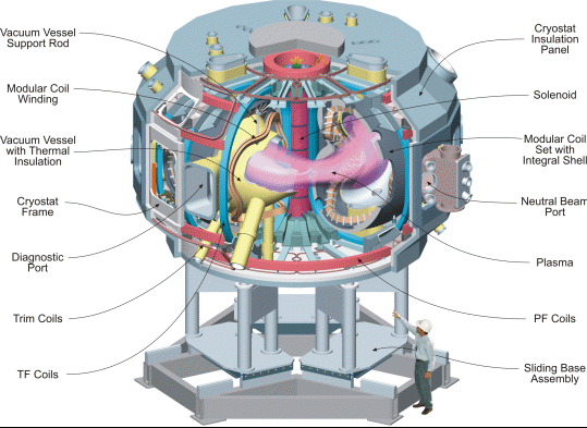
Figure 1 Cut-Away View of the Stellarator Core Assembly
2 Design Requirements and Constraints
2.1Cryostat
The cryostat provides the thermal insulation for the cold coil set and structure, and must seal the coil space from the outside air to prevent condensation on the cold surfaces. The cryostat must also provide a means for circulating dry nitrogen inside the cold volume to cool down and maintain the temperature of the interior structures.
The primary constraints on the cryostat are that it be installed near the end of the overall assembly operation, be easy to remove and replace, and be easy to reconfigure for new diagnostic access requirements.
2.2Machine Support Structure
The machine structure provides the gravity support for the device and the integrated support for the TF and PF coils. The base structure must also minimize the heat leak to the cold structure from the floor, must accommodate the radial thermal contraction of the cold mass, and must provide the sliding mechanism and rails to allow the three field periods to be brought together simultaneously during final assembly (or to be retracted for major modifications or repair). The primary constraints are that it operates at cryogenic temperatures, be non-magnetic, and not interfere with diagnostic or heating access.
3Design Description and Performance
3.1Cryostat
The baseline concept consists of a simple frame and panel design covered with urethane insulation and is illustrated in Figure 2 and Figure 3. The concept includes features recommended by the Alcator C-Mod team based on their experience operating a device with cryogenically cooled copper coils. The frame consists of molded fiberglass modules mounted along the outer perimeter, top and bottom of the external coil support structure. The frames have openings corresponding to the openings in the structure between the TF and PF coils. Fiberglass panels are attached to the frame modules to form a surface for the urethane.

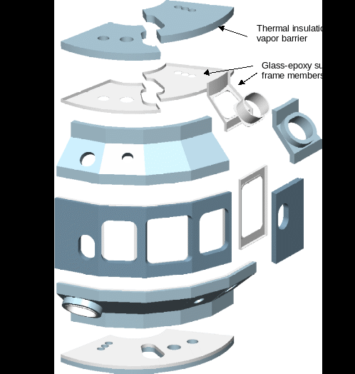
Figure 3 Exploded View of Cryostat
Fiberglass dams are positioned around each vacuum vessel port, coil lead, or utility penetration. Two flexible silicone rubber boots will be used to provide a double seal, with interstital insulation, as illustrated in Figure 4. Dry nitrogen will be bled into the interspace of the boots to exclude any water vapor. After the boots are installed, urethane is then sprayed on the fiberglass panels using a commercial process typically used for large stationary cryogenic tanks. The exterior surface of the urethane is then sprayed with a butyl rubber coating for an additional gas seal and to provide a durable surface. To protect the outer surface from incidental damage during operation, an additional skin of fiberglass panels is planned. For access to interior components, a few removable panels (including the top and bottom central openings) would be provided, but in general, the urethane would simply be removed and a hole cut in the panel where access is desired. The hole would be repaired by patching the panel and re-foaming. This process is analogous to accessing plumbing by cutting holes in a sheet rock wall. During detailed design, an alternate approach using sealed, insulated panels instead of the sprayed on foam will be evaluated.
The urethane insulation is approximately 6 inches thick, which provides good thermal isolation for the cold components (~ 2 kW heat leak). In the event that there are seams or other imperfections that degrade the insulating properties, funding is planned for heaters and blowers to control the outside surface temperature and prevent condensation. Flexible insulation must also be stuffed around the penetrations outside the boots.
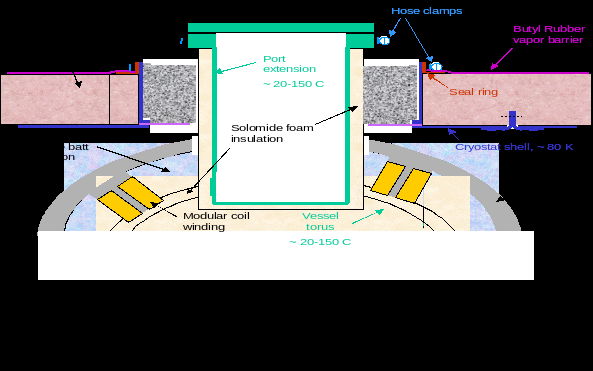
Figure 4 Cryostat Boot Schematic
3.2Machine Support Structure
The machine support structure consists of the base assembly and external coil support structure. These components provide mounting points for all the other components and support the gravity and seismic loads on the device.
Base Assembly
The base assembly is illustrated in Figure 5. A frame is mounted to the floor with three pairs of rails oriented parallel to radial axes through each of the field periods. Retractable carriage assemblies are mounted to the rails to provide a means of assembling the machine in three field periods. The columns are mounted to the carriage assemblies and are tied together in the radial direction for stability. The tops of the columns connect to the underside of the external coil support structure.
The columns will consist of three concentric tubes. The outer tube is attached to the rail carriage and the innermost tube is attached to the cold mass. These tubes are both in compression. Between these tubes is a thinner tube in tension, which provides a long conduction path for reducing heat leakage to the machine. The long tube is mounted such that it can pivot to provide about 0.15 inch compliance in the radial direction to accommodate the thermal contraction of the cold mass. The lateral direction will be constrained with snubbers to resist seismic loads. The concept for insulation between the tubes has not been decided. The best thermal solution is to evacuate the interspace between the tubes, but the more likely choice will be to use a flexible foam insulation between the concentric tubes and around the outside of the outer tube. The entire assembly will be sealed with boots to prevent ingress of water vapor.

Figure 5 Machine Base Assembly
4Design Basis
The design basis for the machine structure and cryostat includes the design criteria and the associated thermal and structural analysis.
Design criteria
The machine base structure will be designed according to the NCSX Structural Design Criteria, which is based on the ASME Code, Section VIII, Division 2. The code provides a conservative but prudent approach to design stresses, fatigue, buckling, and welding of structures.
The cryostat will also be designed to the NCSX Structural Design Criteria to the extent that it applies, but the loading is minimal.
Analysis
The primary loads on the machine base structure are the gravity and seismic loads from the cold structure. The approximate weight of the cold mass is 108 tons. The weights of individual components are summarized in Table 1. A thorough analysis of the base has not yet been performed, but the column size is consistent with the total vertical force assuming only 3 of the 12 columns take the entire vertical load. In addition, the bending strength appears adequate for a lateral force of 0.2g, assuming only 4 columns act to take the load. The sliding rails are locked after assembly, providing a rigid base structure.
The heat leak through the columns will depend on the final design choices, but for a vacuum insulated triple tube design, the heat leak could be as low as 100 W. If a single column design with simple external insulation were used, the heat leak would be on the order of 500 W. Either of these choices would be acceptable.
|
Component/Assembly |
Weight each |
No. |
Total weight |
|
|
(lbs) |
|
(lbs) |
|
Vacuum Vessel |
20,600 |
1 |
20,600 |
|
PFC assembly |
3,000 |
1 set |
3,000 |
|
subtotal, internals |
|
|
23,600 |
|
|
|
|
|
|
Modular Coil 1 |
7,100 |
6 |
42,600 |
|
Modular Coil 2 |
6,700 |
6 |
40,200 |
|
Modular Coil 3 |
7,100 |
6 |
42,600 |
|
TF Coil |
1,300 |
18 |
23,400 |
|
Central Solenoid Assembly |
9,510 |
1 |
9,510 |
|
PF4 |
800 |
2 |
1,600 |
|
PF5 |
2,300 |
2 |
4,600 |
|
PF6 |
1,300 |
2 |
2,600 |
|
Ext. Trim Coils |
7,594 |
1 set |
7,594 |
|
TF Coil support structure, half period |
6,883 |
6 |
41,300 |
|
Subtotal, cold structure |
|
|
216,004 |
|
|
|
|
|
|
Base Structure |
11,143 |
3 |
33,428 |
|
Cryostat |
6,849 |
1 |
6,849 |
|
Misc piping, etc. |
1,000 |
1 |
1,000 |
|
Total Weight of NCSX Core |
|
|
280,881 |
5Design Implementation
5.1Component Procurement and Fabrication
Cryostat The cryostat is procured in three major packages. The first is for the molded frame elements. The intent is to award the entire assembly to one vendor on an evaluated fixed price basis. The vendor would be responsible for fabrication of the molds and panels, trimming and machining, and pre-assembly and fit check. The assembly would be built to a performance specification with geometric and functional requirements, but the vendor would propose the exact method of fabrication. The boots would be procured from a second vendor, also on an evaluated fixed price basis. The process would be similar, using a performance specification and functional requirements. The urethane insulation for the exterior of the cryostat would be awarded to a qualified contractor, who would apply the insulation in place to the completed cryostat assembly.
Base assembly The base assembly is relatively simple, stainless steel welded construction from standard pipe and plate. The intent is to award the entire assembly to one vendor on an evaluated fixed price basis. The vendor would be responsible for fabrication, machining, procurement of slides and rails, and pre-assembly and fit check of all the pieces. The assembly would be build-to-print.
5.2Subsystem Assembly, Installation, and Testing
Cryostat The cryostat is the last component assembled in the test cell. (It is possible that some of the panels could be pre-installed as part of the field period subassembly, but this may make subsequent operations more difficult.) First, the molded frame sections are bolted together in sections and attached to standoffs on the shelf structures. The flat panels in the port openings are then installed along with the conformal dams around each port extension (Fig. 2.1.3-3. The inter-spaces between the dams and the port extensions are packed with batting insulation and the silicon rubber boots are installed between seal rings on the dams and the outside of each port extension flange. The urethane insulation is then applied, followed by the butyl rubber vapor barrier. A fabric or thin sheet metal covering may be included as mechanical protection and a fire retardant, but the choice will not be made until preliminary design. Finally, the cryostat is leak checked to confirm there will be no ingress of air the cold mass.
Machine base assembly The machine base will be pre-assembled by the fabricating vendor. It will be the first component installed in the test cell. The primary steps will be to attach the base frame to the floor with adjustable anchors and grout in place, followed by assembly of the rails, carriages, and columns.
6Reliability, Maintainability, and Safety
A formal Failure Mode, Effects, and Criticality Analysis will not be performed for the cryostat and machine structure until the preliminary design phase. Nevertheless, several design features have been included to enhance the reliability and maintainability of these components.
Cryostat The cryostat can maintain thermal isolation as long as the vapor seal function remains intact. Since this seal is applied as a coating, it can be easily repaired by patching any leaks or trouble spots. In addition, if access is required inside the cryostat for maintenance, it can be disassembled locally, re-assembled, re-insulated and re-sealed with little impact on adjacent areas. The boots that seal the ports are also readily accessible.
Machine base structure The machine base is not expected to have any reliability, maintenance, or safety issues, but all are mitigated by designing the system with a large margin on load capacity of the components.
7Cost and Schedule
The WBS listing and cost estimate for the cryostat and machine structure are summarized in Table 2 and Table 3. This estimate was developed as a bottoms-up estimate, and includes input from potential vendors. Most of the cost is in the cryostat frame and the coil support system, and these estimates were consistent with vendor input.
The Cryostat (WBS 171) is estimated to cost $856K. The Machine Base (WBS 172) is estimated to cost $442K. The recommended contingencies are 25% for the Cryostat and 32% for the Machine Base.
Table 2 WBS listing for Cryostat and Base

Table 3 Cryostat (WBS 15) and Machine Structure (WBS 16) Costs

The schedule for implementing the Cryostat (WBS 171) and Machine Base (WBS 172) may be seen in the Project Master Schedule, provided as part of the Preliminary Design Report. The machine base structure needs to be in place before final assembly in the NCSX Test Cell can begin. Title I design is schedule to begin in mid FY05 and be completed early in FY05. Procured components should all be delivered late in FY05.
The cryostat is not installed until all the field periods have been assembled in the NCSX Test Cell. The exception is the cryostat base, which is installed after the machine base structure is installed and before final assembly begins. Title I design will begin in mid FY03. However, Title II design will not be completed until the end of FY04 because of the many interface details that need to be worked out. Procured components will all be delivered early in FY06. The estimated spending profile is summarized in Table 4
Table 4 Cryostat and Base Assembly cost summary by year of expenditure (WBS Level 2)

8Risk Management
The primary element of risk for both the cryostat and machine structure is cost growth. The main drivers for cost growth are changes to the design concept during preliminary design as a result of changes to the requirements, unfeasible fabrication, or lack of functional performance.
These have been addressed for the cryostat by adopting a simple concept that can be readily modified without affecting other components of the machine. If the heat leak is found to be too high after a more thorough analysis, the thickness of the insulation is increased with very little cost impact. If the structure is too weak, the section depth of the molded panels is modified with very little impact. The concept itself has been discussed with potential vendors and appears entirely feasible to fabricate in its present form. Contact with vendors will be expanded during preliminary design to ensure a feasible and cost effective design.
The machine base risk is addressed in a similar way. There is adequate space for the carriages so slide dimensions and capacity are not an issue. The whole assembly is bolted together, so it can be disassembled and re-assembled without impairing its accuracy (as opposed to welded structures). Finally, there is no new technology to develop for this concept, so no development should be required.
THE DEPARTMENT OF CHEMICAL AND BIOMOLECULAR ENGINEERING COMMITTEE
TISSUE ENGINEERING PERIPHERAL NERVE 251108 PERIPHERAL NERVOUS
( RE)ENGINEERING GENE DELIVERY TOWARD CONSTRUCTION OF ARTIFICIAL VIRUSES
Tags: design document, preliminary design, design, description, document, engineering, cryostat
- PROTOKOLL FRA ÅRSMØTET TIL SVERRE HOVEDLAGET ONSDAG 13 MARS
- THE TIME NEEDED TO COMPLETE A FINAL EXAMINATION IN
- INFORME DE LA EMBAJADA ARGENTINA EN UCRANIA EXPOSICIÓN INTERNACIONAL
- KURZFASSUNG ABSTRACT VORTRAG PFLANZENVIREN IM FORST UND ÖFFENTLICHEN
- UNEPCBDCOPDECXI13 PÁGINA 0 CBD DISTR GENERAL UNEPCBDCOPDECXI13 5 DE
- ERDÉLYI ZSUZSANNA HEGYET HÁGÉK LŐTŐT LÉPÉK ARCHAIKUS NÉPI IMÁDSÁGOK
- OFFICIAL STATISTICS RELEASE POLICY AREA CHILDCARE PROVIDERS AND PLACES
- 30 CATEQUESIS DE LA TERCERA EDAD EL AUMENTO CUANTITATIVO
- INFORME SOBRE EL EVENTO ABRAZO MUNDIAL 2002 DENOMINADO “
- WWWCOPSOQISTAS21NET ANEXO XIV INFORMAR A LA PLANTILLA EN LA
- HTTPWWWECOLEXORGECOLEXLEDGEVIEWRECORDDETAILSDIDPFDSIJSESSIONID1F3D4F053FA3C99060731F529C595A7A?IDLEXFAOC002912&INDEXDOCUMENTS FOREST DECREE 1992 FIJI ISLANDS GOVERNMENT OF THE
- TUTORIAL COMO ACENTUAR LA VETA AL PINTAR UNA GUITARRA
- ¡CUARESMA! ¡CARNAVAL! ¿QUÉ CELEBRAMOS? ANTES DEL INICIO DE LA
- SOURCES OF FUNDS FOR ARMY USE (OTHER THAN TYPICAL
- ROUNDED RECTANGLE 3 WALI KOTA PALU PROVINSI SULAWESI TENGAH
- PAWEŁ ŁĘGOWSKI KOŁOBRZEG 17102005 I ROK – SOCJOLOGIA WYRAŻENIA
- гͻÉÍ³Í 20012017Թ ³Í³·³ÝÁÕ ÝÇËÏÇ ÃÇÍ 3Ü ÁÑÁSSÙ³Ý ՀԱՅԱՍՏԱՆԻ ՀԱՆՐԱՊԵՏՈՒԹՅՈՒՆ
- FOR IMMEDIATE RELEASE NEWS MEDIA CONTACT MARCH 8 2002
- CENTRALNY OŚRODEK BADANIA ODMIAN ROŚLIN UPRAWNYCH (COBORU) RESEARCH CENTRE
- ROZDZIELNIK GMINY W KTÓRYCH STOSUJE SIĘ SZCZEGÓLNE ZASADY ODBUDOWY
- CLIMATE CHALLENGE FUND REPROFILE REQUEST FORM WHAT HAS PROMPTED
- 2 ŠTRUKTÚRA LITERÁRNEHO DIELA LITERÁRNE DRUHY A ŽÁNRE LITERÁRNE
- 64 KRYSTYNA SZYSZKO BARBARA MOSKAL STANISŁAW STASZIC 250 ROCZNICA
- МИНИСТЕРСТВО ОБРАЗОВАНИЯ И НАУКИ РОССИЙСКОЙ ФЕДЕРАЦИИ НИЖЕГОРОДСКИЙ ГОСУДАРСТВЕННЫЙ УНИВЕРСИТЕТ
- INTRODUZIONE IL PRESENTE LAVORO È DIRETTO AD ANALIZZARE IL
- STOFFER OG MATERIALER HVILKE SUNDHEDSFARER KAN DU BLA BLIVE
- GOOD DAY I’D LIKE TO DIRECT YOUR ATTENTION TO
- DIJAKDIJAKINJA ODDELKA GIMNAZIJA KOPER ( IME IN
- NEW COST OPEN CALL NOW PUBLISHED! WE WILL BE
- BOLETIN DE TEMAS DE SALUD DE LA ASOCIACIÓN DE
 HYBRID VEHICLES A TEMPORARY STEP JJ CHANARON1 & J
NA PODLAGI 8 IN 9 ČLENA ZAKONA O DRUŠTVIH
 ROSARIO 28 DE JUNIO DE 2012 DIRECCIÓN PROVINCIAL DE
 F OR CLASS FIVE ROAD SAFETY WHAT IS ROAD
ACC7420 TREATMENT REVIEW COMPLETE THIS REPORT IF YOU’RE A
 WEIGHT LOSS VISIT OUR WEBSITE AT HTTPWWWPHOENIXVAGOV READY FOR
 BEREDSKAPSPLAN VED ARBEIDSKAMPSTREIK KARMØY KOMMUNE APRIL 2014 BEREDSKAPSPLAN
 DON FERNANDO SUÁREZ BARCIA ALCALDEPRESIDENTE DO EXCMO CONCELLO DE
 1º EL DIOS CRISTIANO ES DIOS HIJO DIOS PADRE
KLINIČNI CENTER LJUBLJANA POLJANSKI NASIP 58 LJUBLJANA USPOSABLJANJE DELAVCEV
 NOMBRAMIENTO DEL C CARLOS ANDRÉS MONTES TELLO COMO DIRECTOR
49 SERIE DE ESTUDIOS CULTURALES Nº 9 ORGANIZACIÓN DE
ENGLISH 5 CRITICAL THINKING STUDENT LEARNING OUTCOMES AT THE
 8 PL200502 LOCAL PLANNING APPEAL TRIBUNAL TRIBUNAL D’APPEL DE
BENDRO DARBO IR MOKYMOSI PAMOKOS LIETUVOJE 1 MALŲ VĖRIMAS
 THE TRINITY TRUST SERVICES FOR ENDOWMENT AND EXPENDABLE FUNDS
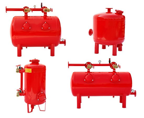 FILTROS DE ARENA SIEMPRE QUE ADQUIRIMOS UN EQUIPO RECIBIMOS
5 TÜRKIYE BANKALAR BIRLIĞI YÖNETIM KURULU BAŞKANI ERSIN ÖZINCENIN
CRIMINAL JUSTICE 101 CASES THESE ARE VERY ABBREVIATED POINT
DEFENSE FEDERAL ACQUISITION REGULATION SUPPLEMENT PART 252—SOLICITATION PROVISIONS AND