MILWAUKEE CITY HALL MUNICIPAL BUILDING AHU10 DX9100 FRONT PANEL
1032 S 16TH ST MILWAUKEE WI 53204 TELE (414)2 THE UNIVERSITY OF WISCONSINMILWAUKEE HELEN BADER SCHOOL OF
ANNUAL EEO PUBLIC FILE REPORT MILWAUKEE RADIO ALLIANCE WLUMFM
BACHELOR OF ARTS IN GLOBAL STUDIES UNIVERSITY OF WISCONSINMILWAUKEE
CS HYDE COMPANY 1351 N MILWAUKEE AVE LAKE VILLA
EARL A BUFORD PRESIDENT AND CEO EMPLOY MILWAUKEE INC
DX-Front Panel Guide
Milwaukee City Hall Municipal Building AHU-10
DX-9100 Front Panel Operation Guide
Analog Input Section
To Display Analog Inputs:
1. Press the [X] key to display analog input 1.
X1 Discharge Air Temp Deg F
2. Subsequent selections of the [X] key will display the following analog inputs.
X2 Return Air Temp Deg F
X3 RA Relative Humidity
X4 Mixed Air Temperature Deg F
X5 Supply Air SP Hi Lim
X6 Supply Air Vel Pres.
X7 SA Humidity HL
X8 Return Air Vel Pres.
3. Press the [XT] key to display the XT’s Analog Input
XT11 Supply Air SP 10th flr
4. Subsequent presses of the [X] key will display the remaining XT’s analog inputs.
To Display Analog Input Alarm Limits:
Press the [X] key to display the desired analog input (see "To Display Analog Inputs").
Press the [A] key to display the analog input low alarm limit.
Press the [A] key again to display the analog input high alarm limit.
Press the [A] key again to return to the analog input value.
To Modify Analog Input Alarm Limits:
Display the desired item to be modified as described above.
Insert the override/adjust key.
Press the [E] key to enter the edit mode, [K] LED will beging to blink.
Use the [] or [] keys to increase or decrease the value.
Press the [E] key to confirm and activate the new value, or press the [esc] key to escape from the edit mode and restore the original value. Remove the key.
Digital Input Section
To Display Digital Inputs:
1. Press the [D] key to display digital input 1.
D1 Low Temp Alarm
2. Subsequent selections of the [D] key will display the following digital inputs:
D2 Filter Status
D3 Supply Fan Status
D4 Return Fan Status
D5 Return Air Smk Detector
D6 Supply Air Smk Detector
D7 DI7
D8 High Static Alarm
3. Press the [XT] key to display the 1st XT’s Digital
D11 Not Used
4. Subsequent selections of the [D] key will display the following digital inputs:
Analog & Digital Output Section
To Display Analog & Digital Outputs:
1. Press the [Y] key to display analog output 1.
{ANALOG} Mixed Air Dampers Control (% Command)
2. Subsequent selections of the [Y] key will display the following:
Y2 {ANALOG} Cooling Coil Valve Control (% Command)
Y3 {DIGITAL} Supply Fan Start/Stop Command Enable (On = Enabled)
Y4 {DIGITAL} 2pos dampr Command Enable (On = Enabled)
Y5 {DIGITAL} Not Used Command Enable (On = Enabled)
Y6 {DIGITAL} Not Used Command Enable (On = Enabled)
Y7 {DIGITAL} Not Used Command Enable (On = Enabled)
Y8 {DIGITAL} Not Used Command Enable (On = Enabled)
Y9 {ANALOG} RETURN FAN VFD Control (% Command)
Y10 {ANALOG} Sup Fan Var SPD Drive Control (% Command)
Y11 {ANALOG} HUMIDIFIER VALVE Control (% Command)
Y12 {ANALOG} Heating Coil Valve Control (% Command)
Y13 {ANALOG} AO13 Control (% Command)
Y14 {ANALOG} AO14 Control (% Command)
3. Press the [XT] key and then the [Y] key to display the next set of XT’s outputs:
Y17 {ANALOG] Not Used
4. Subsequent selections of the [Y] key will display the following:
Y17 {ANALOG} XT1AO7 Control (% Command)
Y18 {ANALOG} XT1AO8 Control (% Command)
To Override Analog or Digital Outputs:
Display the desired item to be overridden, as described in the previous instructions.
Insert the Override/Adjust Key (AS-LCP-0 Key)
Press the [A/M] key to enter the manual mode, [A/M] LED will blink.
Use the [](Up Arrow Button) to turn item on, or the [] Down Arrow Button to turn item Off. Control is now in manual mode.
To Release Outputs:
Display the desired item to be overridden, as described in the previous instructions.
Insert the Override/Adjust Key (AS-LCP-0 Key)
Press the [A/M] key to enter automatic mode, [A/M] LED will be steady, and control has been resumed to automatic.
NOTE: A flashing [A/M] LED indicates that an analog or digital output is in manual mode. A steady [A/M] LED when on a particular Analog or Digital Output indicates that the selected point is in manual mode.
Control Module Section
To Display Control Module Setpoints:
1. Press the [Z] key to display the setpoints for control module 1.
Z1 DAT-PID1 TYPE, SetPoint Value or No Setpoint Value
2. Subsequent selections of the [Z] key will display the following:
Z3 HUM-PID3
Z2 MALL2
Z4 SP-PID4
Z5 RF-PID5
Z6 RAMPS6
To Display Control Module Parameters:
1. Display the desired control module (see "To Display Control Module Setpoints").
2. Press the [A] key to display the process variable.
3. Subsequent selections of the [A] key will display the control module output, proportional band, reset action, rate action, standby bias, off bias and back to the control module setpoint.
Analog & Digital Constant Section
To Display Analog & Digital Constants:
1. Press the [K] key to display analog constant 1.
K1 {ANALOG} ZNT-DIFF
2. Subsequent selections of the [K] key will display analog constants 2-8 and digital constants 1-32.
K2 {ANALOG} OA-T
K3 {ANALOG} WrmUp-SP
K4 {ANALOG} Econ-sp
K5 {ANALOG} MinPos
K6 {ANALOG} MALL-SP
K7 {ANALOG} StaticSP
K8 {ANALOG} RFVol-SP
Digital Constants:
K1 {DIGITAL} ON-OFF Command (On = Enabled)
K2 {DIGITAL} ClgAvail Command (On = Enabled)
To Modify Analog or Digital Constant Setpoints or Command:
Display the desired item to be modified as described above.
Insert the override/adjust key.
Press the [E] key to enter the edit mode, [K] LED will begin to blink.
Use the [] or [] keys to increase or decrease the value.
Press the [E] key to confirm and activate the new value, or press the [esc] key to escape from the edit mode and restore the original value.
Remove the key.
Note: values cannot be changed if an adjust or override command from the METASYS Network is currently active.
JEWISH MUSEUM MILWAUKEE COLLECTION POLICY PURPOSE AND SCOPE OF
MEMORANDUM OF UNDERSTANDING UNITED WAY OF GREATER MILWAUKEE &
MILWAUKEE ART MUSEUM PRESENTS EXHIBITION OF OUTSTANDING EUROPEAN PHOTOGRAPHY
Tags: milwaukee, panel, ahu10, municipal, dx9100, front, building
- SPÓŁKA Z OGRANICZONĄ ODPOWIEDZIALNOŚCIĄ WPIS FORMULARZE
- RAZLAGA DOKUMENTACIJE V ZVEZI Z ODDAJO JAVNEGA NAROČILA ZA
- PARAIŠKA IMUNOBIOLOGINIAMS PREPARATAMS ŠVIRKŠTAMS NR 200 M
- PERSON SPECIFICATION POSITION TITLE EQUIPMENT BROKERAGE MANAGER (TSME2) POSITION
- DEPARTMENT OF HEALTH POLICY TITLE MOBILE WORKFORCE NUMBER 07025
- KÚPNA ZMLUVA ČÍSLO 042016 UZAVRETÁ V ZMYSLE S USTANOVENÍM
- AN AFRICAN UNION GOVERNMENT PERSPECTIVES BY THE SOUTH AFRICAN
- TC ANKARA ÜNİVERSİTESİ EĞİTİM BİLİMLERİ ENSTİTÜSÜ EĞİTİM BİLİMLERİ ANABİLİM
- PRAKUALIFIKASI CSMS 31 PROFIL KONTRAKTOR 1 NAMA PERUSAHAAN
- F ORMULIR DAFTAR ULANG PENERIMA BEASISWA EMAS DATA PRIBADI
- ……………………… GAZDÁLKODÓ J E G Y Z Ő K
- BILAGA 4 ANVÄNDARFALL 12(12) UPPHANDLING AV SCHEMA BEMANNING OCH
- 14 8 GAS FLOW IN PIPES AND POROUS MEDIA
- 6 REVISION OF SECTION 614 FIBER OPTIC CABLE (SINGLE
- INFORMATIONAL PURPOSE DATE FIELDS ON EMPLOYMENT DATA PAGE LINK
- ECF FINANCE COUNCIL MEETING THIS IS MY REPORT ON
- EL CONSELL NOMBRA NOTARIOS Y REGISTRADORES EN LA COMUNITAT
- INFORMATION FOR THE SPRING SEMESTER 2011 UNIVERSITY OF INTERNATIONAL
- МІНІСТЕРСТВО ОСВІТИ І НАУКИ УКРАЇНИ ХАРКІВСЬКИЙ НАЦІОНАЛЬНИЙ УНІВЕРСИТЕТ ІМЕНІ
- LIIKUNTATOIMI IDROTTSVÄSENDET 33 2014 ANVÄNDNINGSINSTRUKTIONER FÖR KONDITIONSSALEN ÖPPETHÅLLNINGSTIDER
- ŽUPANIJSKO POGLAVARSTVO KLASA 02204060318 URBROJ 21701110150601 RIJEKA 4
- VÍDEOS A UTILIZAR EN EL ÁMBITO CIENTÍFICO TECNOLÓGICO DE
- T5 EJERCICIOS DE NÓMINAS CALCULA LAS SIGUIENTES NÓMINAS CASO
- VEČJE NARAVNE IN DRUGE NESREČE V SLOVENIJI V LETU
- CURRICULUM VITAE 1 DATOS PERSONALES NOMBRE Y
- ALMA BASEBALL DRAFT RULES (ONLY HEAD COACHES WILL BE
- POLAND APPLICATION REGARDING PLANNED SCIENTIFIC RESEARCH IN THE POLISH
- SAMMANSTÄLLNING AV LAGSTÖD MED KOMMENTARER TILL VERKSAMHETSKRAV FÖR DJURSKYDD
- NEWS RELEASE SET RECEIVES STRATEGIC WAFER LEVEL PACKAGING EQUIPMENT
- U NIVERSITAT DE LLEIDA ESCOLA TÈCNICA SUPERIOR D’ENGINYERIA AGRÀRIA
(ONDER ACHTERGRONDINFORMATIE EN VOORLICHTINGSMATERIAAL) HANDREIKING PALLIATIEVE ZORG AAN MENSEN
FOR THOSE WANTING TO BEGIN THE RAPIDLY APPROACHING SEASON
 SPEKTROSKOPIOPGAVER SOM KAN LØSES VHJA DATABOGEN OPGAVE 1
STYLES OF LINGUISTIC PEER INTERACTION OF GIRLS AND BOYS
 (REV 2252013) FBI TEEN ACADEMY APPLICATION DENVER DIVISION 2018
 PREFEITURA MUNICIPAL DE GUAÇUÍ ESTADO DO ESPÍRITO SANTO DECRETO
 1 ACÉLOK AUSZTENITESÍTÉSE A LEGTÖBB MELEGALAKÍTÁSI HŐKEZELÉSI ÉS HEGESZTÉSI
INFORME DE PERTINENCIA (ART 5° INCISO A ORD HCS
 TM CSI ORGANIC APICULTURE RECERTIFICATION QUESTIONNAIRE IF YOUR APPLICATION
HEAD OF PAGE THE POINTER TURNS INTO A HAND
POUVOIR JE SOUSSIGNÉ……………………………………… DONNE POUVOIR EN MON NOM
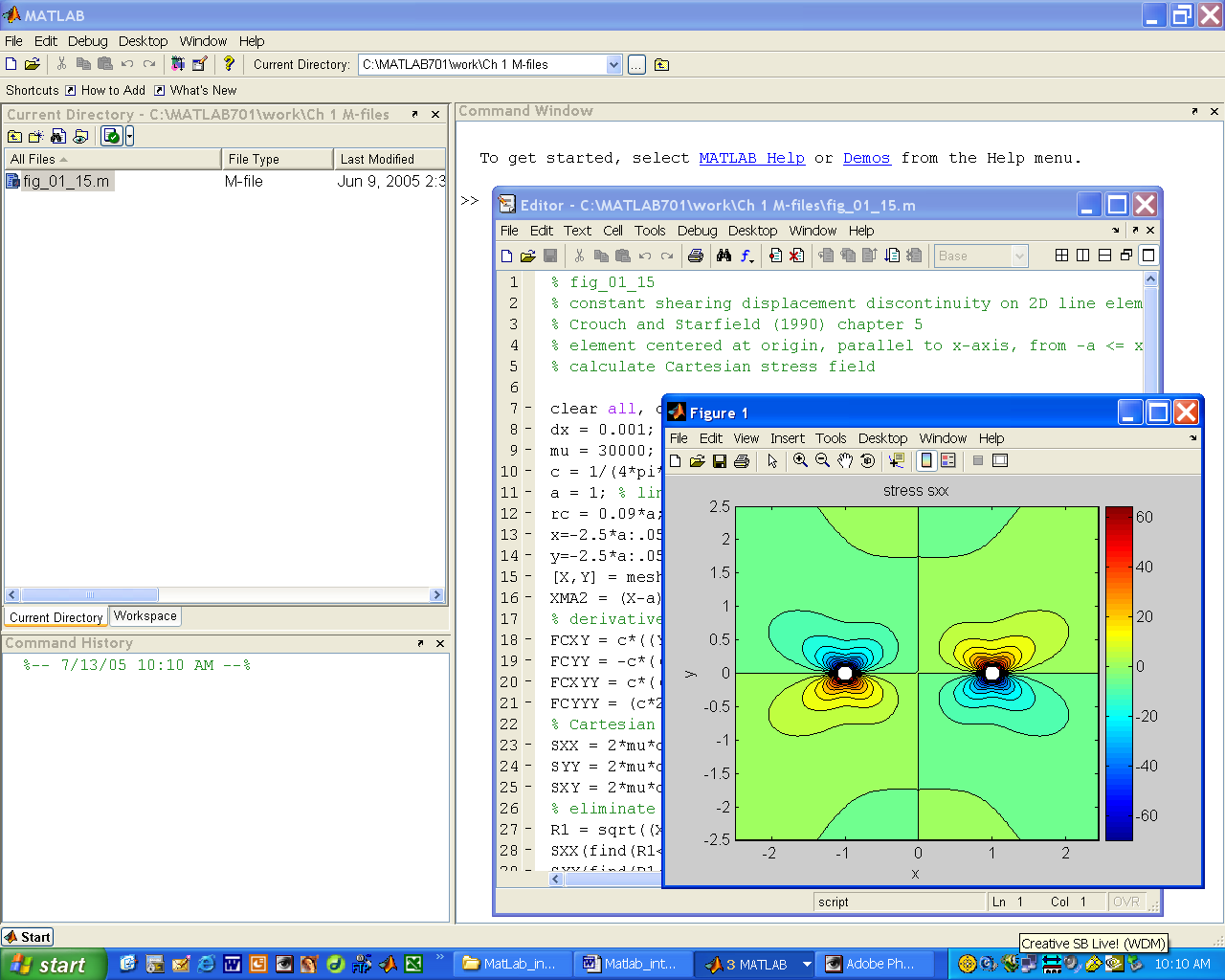 FUNDAMENTALS OF STRUCTURAL GEOLOGY EXERCISE INTRODUCTION TO MATLAB EXERCISE
 INSTITUTIONAL REVIEW BOARD (734) 7125470 HTTPSWWWSTJOESHEALTHORGABOUTUSINSTITUTIONALREVIEWBOARDSTJOSEPHMERCYANNARBOR REVIEW PREPARATORY TO
 SAMTALEKORT ÅNDSFRIHEDSPROJEKTET CASES SAMTALEKORT NR 1 VED HJÆLP AF
 CATERPILLAR DEALERS USED PARTS ASSOCIATION “SECOND LIFE” 33RD
JAK MOTYWOWAĆ SIĘ DO PRACY ZDALNEJ? JAK ORGANIZOWAĆ SOBIE
 B RNĚNSKÁ ASOCIACE FUTSALU BAF POŘÁDÁ POD ZÁŠTITOU ČMFS
 DESIGNATION OF DEPARTMENT SECURITY OFFICER REMINDER DEPARTMENTAL SECURITY OFFICER
INTERESTED CANDIDATES ARE REQUESTED TO SUBMIT THEIR FINANCIAL OFFER
THE 3RD PHILOSOPHY GRADUATE CONFERENCE AT CEU MARCH
