RECONFIGURABLE ADAPTABLE MICROROBOT R LAL TUMMALA1 R MUKHERJEE2 D
CAPÍTULO 4 DESCRIPCIÓN DEL SISTEMA RECONFIGURABLE CAPÍTULO 4PROJECT TITLE MODULAR RECONFIGURABLE SHELLED ROBOTIC AUTOMATION IN FOOD
RECONFIGURABLE ADAPTABLE MICROROBOT R LAL TUMMALA1 R MUKHERJEE2 D
Integration of Environment into Product Design and Manufacturing: Theory and Implementation
Reconfigurable Adaptable Micro-robot
R. Lal Tummala1, R. Mukherjee2, D. Aslam1, Ning Xi1, S. Mahadevan3, J. Weng3
1Department of Electrical and Computer Engineering
2Department of Mechanical Engineering
3Department of Computer Science and Engineering
[email protected], [email protected], [email protected], [email protected], [email protected], [email protected]
Michigan State University, East Lansing, Michigan 48824, USA
ABSTRACT
The research on micro-robots with distributed intelligence, which are capable of reconfiguring themselves to adapt to various defense and civilian tasks, is relatively new. A team of interdisciplinary faculty from the College of Engineering at Michigan State University has taken this challenge and are designing micro-robots that incorporate learning, control and sensing. This paper presents the goals, and directions of this research along with the details of a preliminary design of one of the robots.
INTRODUCTION
Nishi [1-3] , Backes [4] have built large wall-climbing robots with suction cups . However, designing a micro-robot that can climb walls, walk on ceilings, crawl through pipes and traverse on floors is a challenging task. An interdisciplinary faculty in the College of Engineering at Michigan State University have been working on designing such a robot with the support from the Defense Advanced Research Projects Agency (DARPA). The major objective of this research is to design , build and test a prototype micro-robot, that is 1) able to walk, crawl and flip over to climb walls, stairs and navigate through narrow spaces and 2) able to work individually or team up with other robots to perform a mission. We call these robots reconfigurable, adaptable micro-robots. They are called reconfigurable, because they are designed to mechanically reconfigure themselves to provide different forms of locomotion. (Figs 1-3). They are called adaptable because they can adapt to different environments, such as, flat ground, vertical walls, ceilings, stairs, uneven surfaces etc. The design calls for size constraint of 5cm in any direction and completely autonomous. The purpose of this paper is to provide the status of this effort.
ROBOT MECHANISM
The design of this robot was complicated by the constraints imposed by its miniature size and desired
capabilities including autonomous operation and adaptability to different environments such as walls, ceilings etc. Adaptability to operate on walls and floors has been achieved using suction cups. In order to achieve this mode of operation autonomously, we must consider the following:
Size: The robot must measure less than 5cm in any dimension.
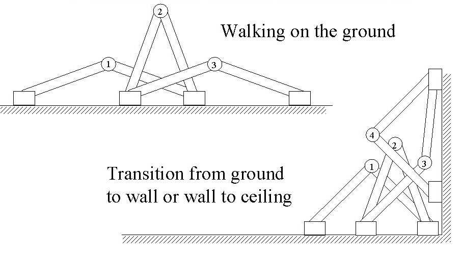
Fig. 1.
Walking motion
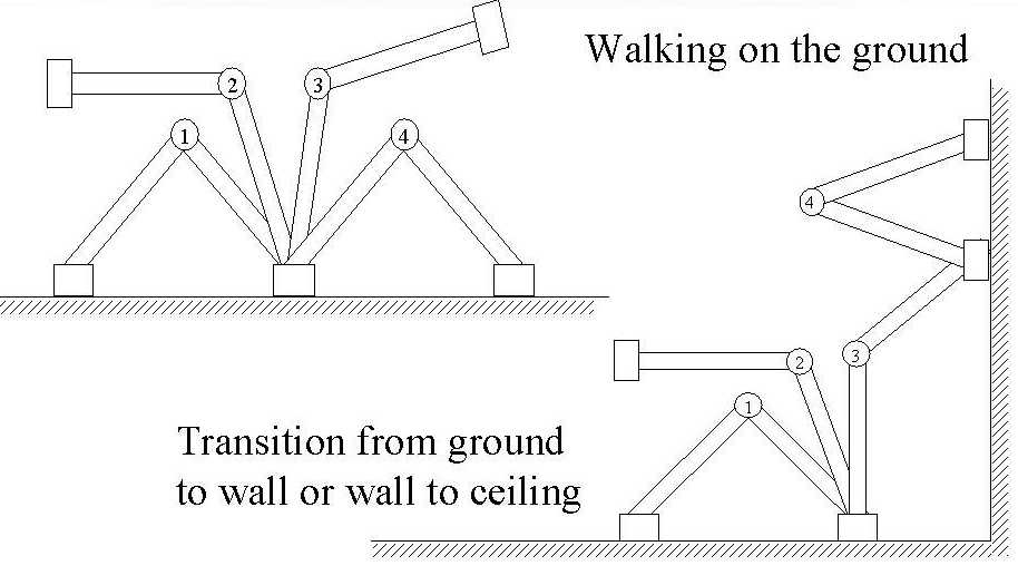
Fig. 2.
Flip over motion
Weight Limitations: Suction cups that are limited in size support the robot. Since the holding capacity of a suction cup is proportional to both achievable vacuum level and suction cup diameter, the holding capacity of the foot is also limited. Consequently, net robot weight is the most substantial constraint.
Actuator Limitations: While the frame structure of such a robot can be quite lightweight, actuators contribute significantly to net robot weight. The number of degrees of freedom, number of actuators and the robot weight are related. As we increase the number of degrees of freedom, the robot weight will increase and will become excessive. For this reason, special attention must be given to use as few actuators as possible through novel joint structure, minimal degrees of freedom, and frame optimization.
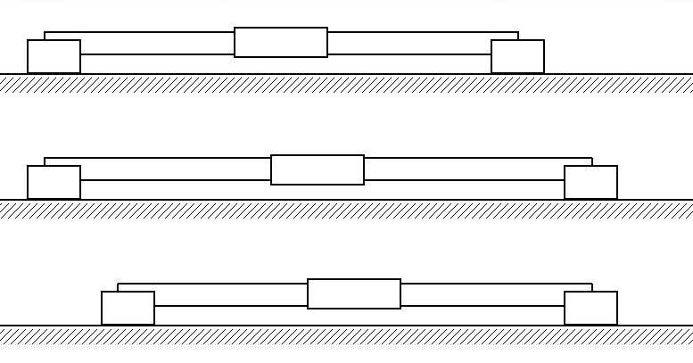
Fig 3. Crawling motion
Control Strategies: The importance of intelligent and efficient control strategies is all the more important given the reduced DOF and maneuverability discussed above. The computational resources and available sensors ultimately limit the capabilities of the control strategies.
Intelligence: On a robot of this size, very limited space is available for memory, sensors, actuator controllers, and processing units, all of which contribute to intelligent autonomous operation. The design must use all available space to incorporate these traditionally solid state components.
Power supply: Besides actuators, power supplies such as batteries contribute most substantially to weight. Dense power sources as well as efficient actuators are paramount.
Based on the above considerations, a number of kinematic structures were evaluated and as a preliminary design, a biped structure with four joints driven by three actuators was chosen. A diagram of this robot is shown in Fig. 4. It consists of two legs supported by the suction cups. The three degrees-of - freedom of the robot are indicated on the diagram by the symbols , , and . Note that angle is indicated on joints 2 and 3 as and 2, respectively. A single actuator mounted on link 2 drives these joints via a belt drive with a 2:1 reduction coupling them. The DOF at joint 1 is driven independently of joints 2 and 3 by an actuator mounted on link 2 and facilitates walking motion. The DOF at joint 4 is driven via a differential (not shown) intersecting Joint 3 and a by a motor mounted on Link 3. The DOF permits steering capabilities for the robot. By reducing the number of actuators in this manner minimizes weight while provide additional package space for solid state components and power sources.

Fig. 4. Micro-robot
3. SMART ROBOT FOOT (SRF) DESIGN
Robotic
foot consists of a suction cup, vacuum pump and an aluminum
connector as shown in Fig 5. A strengthening ring was provided on
the cup neck to prevent bending under parallel load. It weighs
approximately 31 grams and incorporates pressure sensor housing
between the pump and the suction cup. A shape memory alloy based on
Titanium and Nickel micro-valve is incorporated to control the
release time. The views of robotic foot on the wall and the metal
cabinet are shown in F
ig.
6. More details are given in a forthcoming paper. [5]
KINEMATICS
4.1 Coordinate frames assignment
Usually
the analyses of biped walking are based on the assumption that the
motion in the sagittal plane is not affected by the motion in the
lateral plane. For this reason, in most of the previous studies the
kinematics and dynamics of the biped robots are considered
separately and in different planes. However, since the movements of
our walking robot in sagittal and lateral planes are coupled, this
traditional approach is not applicable here.

Because the structure of robot requires that at least one foot remains contact with the surface all times, the setup of the coordinate frames are assigned in three-dimensional space with respect to right-foot supporting (RFS) phase and left-foot supporting (LFS) phase. The assignment of coordinate frames is given using D-H convention in RFS and LFS phases as shown in Figs. 7 and 8.
For
example, in the RFS phase the base coordinate frame is attached to
the right foot which is fixed on the surface. The left foot can move
freely, with the “hand coordinate frame" attached.
The
vectors
![]() represent the position and orientation of the end-points. Note, in
this design the length of link 2 equals to the length of link 3 (see
Fig.4).
represent the position and orientation of the end-points. Note, in
this design the length of link 2 equals to the length of link 3 (see
Fig.4).
4
.2
Forward kinematics
In RFS phase, the forward kinematics of the robot can be
written as:
where:
![]()
![]()
![]()
![]()
![]()
![]()
![]()
![]()
![]()
![]()
![]()
![]()
where
![]() ,
,
![]() represent
the function
represent
the function
![]() ,
respectively.
,
respectively.
In LFS phase:
![]()
![]()
![]()
![]()
![]()
![]()
![]()
![]()
![]()
![]()
![]()
![]()
where
![]() .
Note that
.
Note that
![]() to
to![]() are
defined in the corresponding coordinate frames in RFS and LFS phase.
are
defined in the corresponding coordinate frames in RFS and LFS phase.
A detailed analysis is given in Yue et.al [6].
SYSTEM OVERVIEW
The system overview is given in Fig. 9. At the lowest level each joint is controlled by a PIC based controller. These controllers are of PID type. The inputs for each controller are : position, velocity and acceleration. The status of each joint is obtained through an encoder. The robot has infrared sensors for communication and a micro-camera for visual input. These robots are designed to work individually or as a group. They also can work with other devices and/or robots using different modes of communication.
We now describe the proposed software architecture of the robot in more detail. The overall demonstration plan that we are working toward requires a team (up to three) of the wall-climbers to work together to build up a situational awareness of the environment. This capability requires the robots to navigate around an environment,
learn the structure of the environment, and transmit information back to the host receiver.
The software architecture is decomposed into the following components:
Reactive planner: Behavior-based architectures are a well-known framework for programming mobile robots [7]. We use this approach for the reactive planner. One example of the type of behavior that will be implemented on the wall-climber is “homing” towards a designated target. The target location could be a window (on a wall), or it could be a specific point on the window. Both individual and group behaviors are being implemented. The group behaviors will require inter-robot communication, which is being tested using radio as well as infrared technologies. The robots will send each other short coded messages, which could represent motion commands, sensor data, or system status (e.g. battery level).
Task planner: One problem with behavior-based robots is the lack of flexibility in achieving different goals (e.g. homing towards a target may require a different set of behaviors than tracking a wall, or going through a narrow pipe). The role of the task planner is to select an appropriate subset of behaviors for the particular goal (which could be input by the user). The task planner also uses a sparse representation model of the environment in directing the movement of the robot. For example, if the robot’s goal is to go towards a window, the task planner uses a model of the wall to direct the movement of the robot away from obstacles. The model of the environment need not be explicit. For example, the robot could be trained online by collecting sample images labeled with the correct behavioral response in those situations (i.e. supervised learning, as described in [8] and [10]), or it could be trained by delayed feedback (i.e. reinforcement learning, as described in [9]).
Sensory processing: The wall-climber will be equipped with a variety of low-dimensional sensors (e.g. ambient light infrared sensors), as well as high-dimensional sensors (e.g. a micro-camera). Reactive behaviors, such as avoiding obstacles or homing, will use both types of sensors. The task planner will learn a model of the environment by combining low-dimensional and high-dimensional sensor representations.
CONCLUDING REMARKS
In this paper, preliminary details of a reconfigurable robot are discussed. It has a biped structure with suction cups at its extremities and is designed to climb walls, and crawl on ceilings. More details along with the experimental results will be presented at the conference.
REFERENCES
Akira Nishi and H. Miyagi, "Simulation and test of a flight type wall-climbing robot", Proc. World Automation Congress (WAC'96), pp.569-576, 1996.
A. Nishi, "Development of Wall-Climbing Robots", Computers and Electrical Engineering, Vol. 22, No. 2, pp.123-149, 1996.
Akira Nishi, "A Biped Walking Robot Capable of Moving on a Vertical Wall", Mechatronics Vol. 2, No.5, pp.543-554, 1992.
Paul G. Backes et.al , " The Multifunction Automated Crawling System (MACS), ", Proceeding of IEEE International conference on Robotics and Automation, Albuquerque, New Mexico, pp. 335-340, 1997.
G. Dongi and D. Aslam " Design, Fabrication and Testing of robotic foot for micro-robots" , to appear
Meng Yue, Mark Minor, , Ning Xi, and Ranjan Mukherjee, " Kinematics workspace analysis of a miniature walking robot", to be presented at IROS conference, Korea, 1999.
R. A. Brooks, “A robust layered control system for a mobile robot”, IEEE Transactions on Robotics and Automation, vol. 2, no. 1, pp. 14-23, 1986.
S. Mahadevan, G. Theocharous, N. Khaleeli, “Rapid concept learning for mobile robots”, Autonomous Robots, vol. 5, pp. 239-251, 1998.
S. Mahadevan and J. Connell, “Automatic Programming of Behavior-based Robots using Reinforcement Learning”, Artificial Intelligence, vol. 55, pp. 311-365, 1992.
J. Weng and S. Chen, ``Vision-guided navigation using SHOSLIF,'' Neural Networks, vol. 11, pp. 1511-1529, 1998.
Acknowledgment
This work is supported by the Defense Advanced Research Projects Agency, DARPA contract No. DAANO2-98-C-4025.
Tags: adaptable micro-robot, called adaptable, reconfigurable, adaptable, microrobot, tummala1, mukherjee2
- OCTOBER 28 2021 HERE IS HOW THE PROGRAM WORKS
- 50 FESTIVAL HRVATSKIH KAZALIŠNIH AMATERA STARI GRAD NA HVARU
- NATIONAL SECURITY FRAMEWORK 31 SEARCHING OF THE PERSON THIS
- PROTECTORES DE LOS OJOS Y DE LA CARA PERMITEN
- REJON 6 LP IMIĘ I NAZWISKO SZKOŁA REJON KOD
- SKS YEMEKHANE TALİMATI DOKÜMAN NO TL026 İLK YAYIN TARIHI
- Collection and no Cost Shipping Procedures for Mercury Switches
- APPENDIX 1 SPECIAL STAMP ISSUE – “HEARTWARMING II”
- TUTORÍA CAPACIDAD CRÍTICA DILEMAS MORALES OBJETIVOS 1 ADOPTAR UNA
- Village of Spring Groverichmond 2019 Springsummer Recreation Registration Form
- FORMULIR AKADEMIK FORMULIR PENGAJUAN TUNDA REGISTRASI YTH DEKAN FAKULTAS
- s Pring Grove Police Department Chief Paul j Folz
- WZÓR METAPLANU PROBLEM CHOROBY UKŁADU KRĄŻENIA JAK BYĆ POWINNO?
- 20102011 LIBROS GRATUITOS A COMPRAR CON TARJETA DE LA
- Spring 2009 Calendar jan 14 (w) Classes Begin jan
- DUNWORTH & ASSOCIATES EXECUTIVE SUMMARY THE FINDINGS OF
- PERSYARATAN PENDAFTARAN UJIAN AKHIR PROGRAM PROGRAM STUDI S1 PETERNAKAN
- ERNEST HEMINGWAYS A CAT IN THE RAIN COMMENTARY BY
- 1741 ANAIS DO 47º CONGRESSO BRASILEIRO DE CERÂMICA PROCEEDINGS
- PROGRAMA D’ACTIVITATS TARDORHIVERN 2009 CAP ROGER DE FLOR
- IN HIGH SCHOOL BASEBALL ALL STARTERS MAY LEAVE AND
- PROBLEMAS REPASO FISICA PROFESORFÉLIX MUÑOZ DINÁMICA Y GRAVITACIÓN PROBLEMA
- Listen a Minutecom Spring one Minute a day
- 1 STUDENT AND PLACEMENT DETAILS ACADEMIC YEAR DEPARTMENT COURSE
- ZAHTJEV ZA POTPORU PO OSNOVI ULAGANJA U PODIZANJE TRAJNIH
- INTERVENCIÓN DEL PRESIDENTE DE LA REPÚBLICA RAFAEL CORREA EN
- 18 TUMAN ROTHJOHNSON BAKER AND VECCHIO AUTISM AND SPECIAL
- RADICADO NO 2015 00161 01 ACCIONANTE JORGE ARTURO RUIZ
- EJERCICIO 10 A CONTINUACIÓN OS CUENTO COMO REALIZAR EL
- COURSE TITLE HYDROGEN NETWORK PART I LECTURERS CHRISTIAN
 EL SERVICIO NAVARRO DE SALUD UTILIZA POR PRIMERA VEZ
VRIJSTELLING OP BASIS VAN EERDER VERWORVEN COMPETENTIES (EVC) A
EMPRESA PORTUARIA QUETZAL EPQ DEPTO COMPRAS DOCUMENTO CON PREGUNTAS
REVIEWING REVISED STATE PLANS MEETING THE HIGHLY QUALIFIED TEACHER
 LESSON ELEMENT EXPERIMENTAL DESIGNS INSTRUCTIONS AND ANSWERS
SUPPORTING PEOPLE OUTCOMES CORE SET GUIDANCE KEY PRINCIPLES
 WORK EXPERIENCE PARENTAL CONSENT FORM I AGREE TO (STUDENT
HDF EN LÍNEA (N 358) HD BAJO FLUJO
TIPO E CODIGO DE CARRERA 42 CÓDIGO DE ASIGNATURA
DECEMBER 2020 MANUAL OF PERSONNEL PRACTICE SCHOOL GOVERNING BODIES
DEPARTMENT OF ENGLISH UNIVERSITY OF PUERTO RICO MAYAGÜEZ PUERTO
 GRADE 7 MODULE 4B UNIT 2 LESSON 9 GATHERING
NA TEMELJU ČLANKA 54 I 80 STAVKA 3 I
SUMMARY NOTES MEETING UNIVERSITYLEVEL ADVISORY COMMITTEE FOR GENERAL EDUCATION
 LA II MUESTRA DE TEATRO PROFESIONAL COMENZARÁ EL PRÓXIMO
OSNOVNI SUD U BANJOJ LUCI PO SUDIJI DEJANU PETRIČIĆU
 PROF ÓSCAR GARRIDO C LENGUAJE Y COMUNICACIÓN NB4 PRUEBA
 THE EASY WAY TO PASS EXAMS DAYS AND WEEKS
 ОБЩЕШКОЛЬНАЯ ЛИНЕЙКА БЛОКАДА ЛЕНИНГРАДА В ВЕЛИКОЙ ОТЕЧЕСТВЕННОЙ
 PROCESO DEL ACOGIMIENTO FAMILIAR POR COMUNIDADES AUTÓNOMAS SERVICIO MULTICANAL
