SUPPLEMENTARY MATERIAL (ESI) FOR LAB ON A CHIP THIS
PRACTICE NOTE SOURCING SUPPLEMENTARY EMERGENCY RESPONSE RESOURCESSUPPLEMENTARY MATERIAL (ESI) FOR CHEMICAL COMMUNICATIONS THIS
(SUPPLEMENTARY ORDER PAPER) 19 DÁIL ÉIREANN DÉ MÁIRT 2
1 SUPPLEMENTARY MATERIAL FOR PERKIN TRANSACTIONS 1 THIS JOURNAL
1 SUPPLEMENTARY MATERIALS SUPPLEMENTARY TABLE 1 DESCRIPTION OF DES
1 SUPPLEMENTARY TABLE 1 CATEGORIZATION OF THE 120 NODULES
Supporting Online Material for
Supplementary Material (ESI) for Lab on a Chip
This journal is © The Royal Society of Chemistry 2007
Electronic Supplementary Information for
Multifunctional Microvalves Control by Optical Illumination on Nanoheaters and Its Application in Centrifugal Microfluidic Devices
Jong-Myeon Park†, Yoon-Kyoung Cho†, Beom-Seok Lee, Jeong-Gun Lee*& Christopher Ko*
†First two authors contributed equally. *To whom correspondence should be addressed.
E-mail: *[email protected] & *[email protected]
Electronic Supplementary Information includes 3 Movie files, 3 Figures and 1 Table.
Movie file 1.
- A movie file showing the operation of NC-LIFM (Normally Closed Laser Irradiated Ferrowax Microvalves).
- Upon the laser irradiation started at 0.407 sec, the ferrowax is melted away and the channel was open at 0.419 sec. Therefore, the response time to open the channel was determined to be 0.012 sec.
Movie file 2.
- A movie file showing the operation of NO-LIFM (Normally Open Laser Irradiated Ferrowax Microvalves).
- Upon the laser irradiation started at 1.222 sec, the molten ferrowax is burst into the main channel and close it at 1.666 sec. Therefore, the response time to seal the channel was determined to be 0.444 sec.
Movie file 3.
- A movie file showing the total process of centrifugal microfluidics using LIFM.
- Detail description is shown in Fig. 4. and the corresponding text.
Fig.
S1. (A) Schematic diagram of the test chip with NC-LIFM (B)
the side view of the LIFM fabrication procedure. (i) As the
molten ferrowax is injected into the ferrowax inlet hole, it flows
into the microchannel by capillary action and blocks the main
channel as it is solidified. (ii) The excess amount of the
molten ferrowax flows into the AVC(Assistant Valve Chamber).
(iii) The valve length could be controlled by adjusting
the distance between the ferrowax injection hole and the AVC
position. For example, if the top plate is positioned as the dotted
line, the valve length is decreased and so does the LIFM volume. (C)
The dispensing ferrowax was automatically controlled by a
custom-designed instrument equipped with CD heater, CCD camera, X-Y
stage and a syringe installed with a ferrowax heater.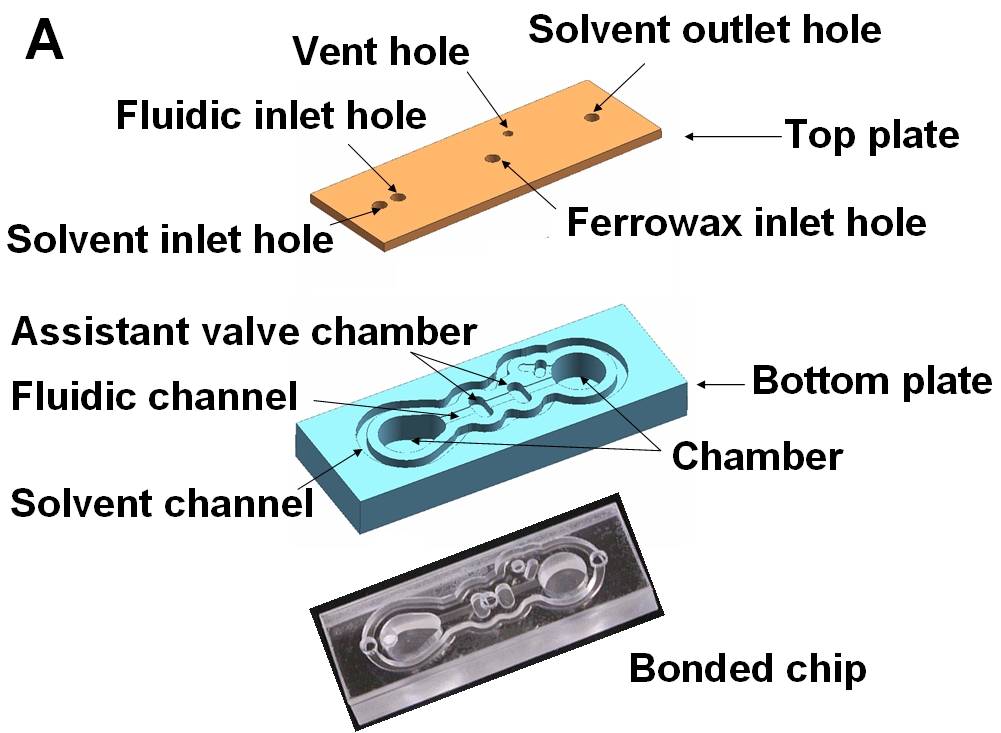
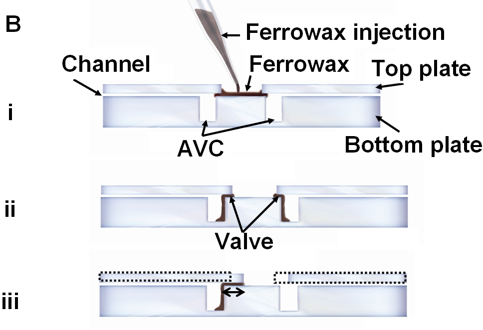

Fig.
S2 Schematic diagram of the ferrowax valve operation on a CD. In
order to transfer liquid from reservoir A to reservoir B, the CD is
rotated with the angle θ to the laser home and the laser diode
is moved to the valve position with the distance (r-r0).
Then, laser with power of 1.5 W was applied for 1 sec to melt the
ferrowax and the disk is spin to pump liquid from reservoir A to
reservoir B.
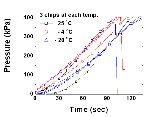
Fig.
S3 Test chips with preloaded ferrowax kept at -4 ℃,
-20 ℃, and
25 ℃ for
two months were used for leakage tests. In all of the cases, the
maximum hold-up pressure was larger than 400 kPa. For clear
visualization, only 10 data points were shown in symbols among more
than 3000 data.

Table
S1.
A spin program
for the microfluidics on a CD
Spin
No. Spin
speed (Hz) Time
(sec) Operation - - - Input
0.1 N NaOH solution (blue) 50 L
to chamber 1 (Fig.
4B). Input
0.1 N HCl (yellow) 50 L
to chamber 2 (Fig.
4B). Input
0.1N NaOH (blue) 50 L
to chamber 3 (Fig.
4B). 1 30 5 LIFM
1 opened, blue solution transfer to chamber 4 from chamber 1
(Fig.
4C). 2 30 5 LIFM
2 opened, yellow solution transfer to chamber 4 from chamber 2
(Fig.
4D).
3 +
9 ~ - 9 12 Mixing,
Color changes from blue to yellow by neutralization (Fig.
4E). 4 30 5 LIFM
3 opened, defined-volume of 50 L
in
chamber 4 is transferred into chamber 7 (Fig.
4F). 5 - - LIFM
4 closed (Fig.
4G). 6 30 5 LIFM
5 opened, blue solution in chamber 3 is transferred into chamber
4 (Fig.
4H). 7 +
9 ~ - 9 12 Mixing,
Color changes from yellow to blue (Fig.
4H). 8 30 5 LIFM
6 opened, defined-volume 50 L
in chamber 4 is transferred into chamber 5 (Fig.
4I). 9 30 5 LIFM
7 opened, defined-volume 50 L
in chamber 4 is transferred into chamber 6 (Fig.
4J).
10 SUPPLEMENTARY DATA FOR “THE VACUUM UV PHOTOABSORPTION SPECTROSCOPY
11 Supplementary Record Form Advanced Livestock Record Rabbits 20to
12 SUPPLEMENTARY MATERIALS THIS FILE CONTAINS THREE SUPPLEMENTARY TABLES
Tags: (esi) for, supplementary, material, (esi)
- Ideal Regression the Following Scatterplots Regression Tables and Diagnostic
- CONSEJO DE GLOMERULOPATÍAS ANBA CURSO ANUAL DE GLOMERULOPATÍAS AÑO
- 202022 ROUND 2 – JUNIOR HIGHMIDDLE SCHOOL SCORESHEET SCHOOL
- APEC LIFE SCIENCES INNOVATION FORUM REGULATORY HARMONIZATION STEERING COMMITTEE
- JUAN – SOLAMENTE HACE DOS DÍAS QUE HE VUELTO
- APELLIDO1AUTOR1 APELLIDO2AUTOR1 N Y APELLIDO1AUTOR2 APELLIDO2AUTOR2 N REVESCO (XXX)
- KEMENTERIAN PENDIDIKAN DAN KEBUDAYAAN POLITEKNIK NEGERI MALANG JALAN SOEKARNO
- 20082009 NEVELÉSI ÉV MUNKÁJÁNAK ÉRTÉKELÉSE HÉTSZÍNVIRÁG ÓVODA 1118 BUDAPEST
- UNIDAD 19 CONCEPTOS DE LEXICOLOGÍA Y SEMÁNTICA ANTÓNIMOS
- RFID CONDUCTIVE INKS XZ250 – THERMAL FLEXIBLE CONDUCTIVE
- 0 MINISTERIO DE RELACIONES EXTERIORES CMRREEXIVDT 3
- P O Š T U J T E N
- BETLEMS AL CENTRE DE PALMA NADAL 2008
- ANG PANIMULANG PAGHAHAHANAP SA ANACBANUA SA PAGBASA NG PANITIKANG
- 4 CARTA A LOS DISCÍPULOS (12) DESDE SAN SALVADOR
- CONSILIUL MUNICIPAL ORHEI PROIECT D E C I Z
- CONGREGAZIONE PER LA DOTTRINA DELLA FEDE ISTRUZIONE SULLA VOCAZIONE
- NOMBRE DEL DOCUMENTO INSTRUCTIVO DE TRABAJO PARA ELABORAR PROCEDIMIENTOS
- DETECCIÓN DE NECESIDADES FORMATIVAS DE LOS FUTUROS TRABAJADORES EN
- GTRIMSN2REV20 PAGE 41 WORLD TRADE ORGANIZATION GTRIMSN2REV20 3 SEPTEMBER
- AZ ÉPÍTŐIPARI SZAKKÉPZÉS HELYZETE ÉS TOVÁBBFEJLESZTÉSE AZ ÉPÍTŐIPARI SZAKKÉPZÉS
- 7 TEMA ÍNDIOS IGREJA NOVOS DIÁLOGOS FALAR SOBRE A
- GUIDELINES FOR INTERNATIONAL COMMODITY TRADING PLATFORM AND CARRIER COOPERATION
- MATERIAL SAFETY DATA SHEET CAREDOM (REPORTE DE SEGURIDAD)
- SNACK SHACK SIGN UP FORM (EXAMPLE) NCR FORM MUST
- 3 10002 ZAGREB HRVATSKA ILICA 49II PP 166
- GÜNDE 1 Mİ2 Mİ YOKSA HİÇ Mİ? TÜRKIYEDE
- A406 PÁGINA 4 OMPI S A406 ORIGINAL INGLÉS FECHA
- A LA SOMBRA DE LA
- “EVERY SYSTEM OF SCIENTIFIC THEORY INVOLVES PHILOSOPHICAL ASSUMPTIONS” TALCOTT
RESOLUCIÓN NO 0920 DE 2011 ( 18 DE AGOSTO
 DUNAREA & DELTA – TARG INTERNATIONAL PENTRU DEZVOLTAREA MACROREGIUNII
Ðïࡱáþÿ ¬®þÿÿÿª«±¥ág ¿®«bjbjx8eùx8eù Åbì³ì³g¥x89ÿÿÿÿÿÿ] ¤¤¤xxxx8°ì4xk(äþ(& &
ON MONDAY FEBRUARY 9 2004 THE PREBLE TOWN BOARD
 FOR THE ATTENTION OF PHYSICAL EDUCATION TEACHERS FACILITATED BY
SACRED SPACE AND THE NATURAL WORLD THE HOLY WELL
 MOD 14 BIS COMPILATO A CURA DEL SUAP PRATICA
PHOENIX COLLEGE ACADEMIC AFFAIRS INSTRUCTIONAL SUPPORT SERVICES SPECIAL PROJECTS—298
 3 ANÁLISIS DEL CENTRO EDUCATIVO EN SU
  PROCESO ADQUISICIÓN DE BIENES Y SERVICIOS FORMATO ESTUDIOS Y
 DISABLED PERSONS PARKING SCHEME APPLICATION THIS FORM HAS
A KUTATÓMUNKA ELISMERÉSE A DOKTORI KÉPZÉSBEN (TELJES IDEJŰ ILL
 A ACTIVITAT TÍTOL DE L’ACTIVITAT NOM TÍTOL DE
01720305 ZUSTELLUNG VON SCHRIFTSTÜCKEN IN VERWALTUNGSSACHEN IM AUSLAND EUROPÄISCHES
 ASHFIELD DISTRICT COUNCIL COMPLAINT FORM HIGH HEDGES USE THIS
ANLAGE ZUM KAUFVERTRAG MIT DER ANNAHME DES AUFTRAGES VERPFLICHTET
OAMGMAMR – FILIALA OLT FIȘA POSTULUI ASISTENT MEDICAL BALNEOFIZIOTERAPIE
¿JESÚS USABA TÚNICAS “DE MARCA”? J KWABENA ASAMOAHGYADU [INTRODUCCIÓN]
PAGOS DESDE COLOMBIA A ESPAÑA (II) DE ACUERDO CON
 ARTE VINI SPOL S RO A RTE VINI IS
