ENGINEERING TRIPOS PART IB PAPER 8 – ELECTIVE (2)
3 DUPONT ENGINEERING POLYMERS PLANEA PRODUCIR UNAEARTHQUAKE ENGINEERING RESEARCH INSTITUTE OREGON STATE UNIVERSITY
FACULTY OF ENGINEERING AND PHYSICAL SCIENCES TAUGHT
GR5N 22 SVQ PERFORMING ENGINEERING OPERATIONS AT SCQF
JOB DESCRIPTION DEPARTMENT ENGINEERING JOB TITLE ASSESSOR
Teach Engineering Stem Curriculum Lesson Designing Bridges
1
ENGINEERING TRIPOS PART IB
PAPER 8 – ELECTIVE (2)
Mechanical Engineering for Renewable Energy Systems
Lectures 4, 5 and 6
Dr. Digby Symons
Design of Wind Turbines – Blade aerodynamics, Loads & Structure
Student Handout
CONTENTS
4 Wind Turbine Blade Aerodynamics 3
4.3 Wind Turbine Blade Kinematics 7
More detailed coverage of the material in this handout can be found in various books,
e.g. Aerodynamics of Wind Turbines, Hansen M.O.L. 2000
4Wind Turbine Blade Aerodynamics
4.1Introduction
4.1.1Aim
Preliminary design of a wind turbine:
4.1.2Wind turbine type
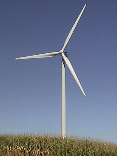
Horizontal axis wind turbine (HAWT) with 3 blade upwind rotor – the “Danish concept”:

4.1.3Load cases
We will consider two load cases:
1) Normal operation – continuous loading
Aerodynamic, centrifugal and self-weight loading
2) Extreme wind loading – storm loading with rotor stopped
4.2Aerofoil Aerodynamics
4.2.1Lift, drag and angle of attack

4.2.2Lift and drag coefficients
Define non-dimensional lift and drag coefficients
4.2.3Variation of lift and drag coefficients with angle of attack
How does lift and drag vary with
angle of attack
![]() ?
?

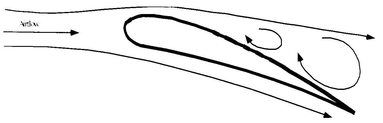
Stall:
4.2.4Application of 2D theory to wind turbines
Tip leakage means flow is not purely two dimensional
Wind turbine blades are
spinning with an angular velocity
![]()
The angle of attack depends on the relative wind velocity direction.
4.2.5Example aerofoil shape used in wind turbines
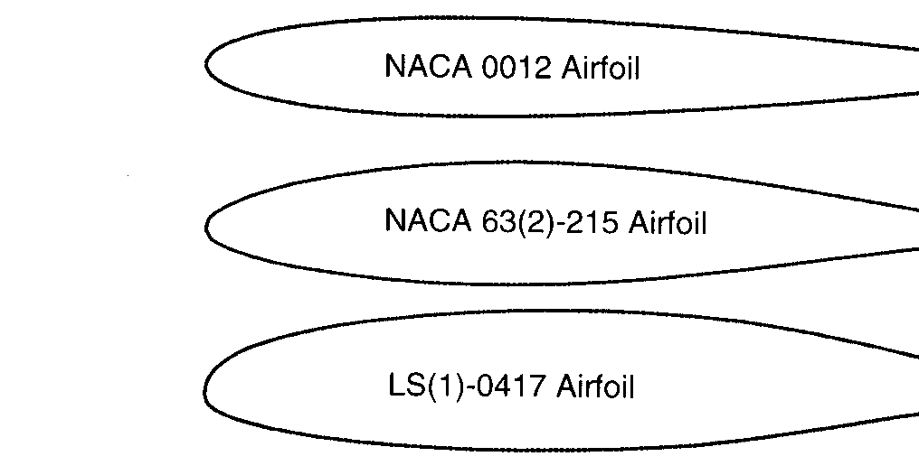


Lift and drag coefficients for the NACA 0012 symmetric aerofoil (Miley, 1982)

4.3Wind Turbine Blade Kinematics
4.3.1Blade rotation


4.3.2Wake rotation

a = axial induction factor
a’ = angular induction factor
4.3.3Annular control volume
Wake rotates in
the opposite sense to the blade rotation
![]()

4.3.4Wind and blade velocities
Induced wind velocities seen by blade + blade motion

Local twist angle
of blade =
![]()
4.3.5Blade relative motion and lift and drag forces

Local angle of
attack =
![]()
Relative
wind speed
![]() has direction
has direction
![]()
where
![]()
and
![]()
![]() and
and
![]() are aligned to the direction of
are aligned to the direction of
![]()
Obtain
![]() and
and
![]() for
for
![]() from table or graph for aerofoil used
from table or graph for aerofoil used
4.3.6Resolve forces into normal and tangential directions

We can resolve lift and drag forces into forces normal and tangential to the rotor plane:
We can normalize these forces to obtain force coefficients:
Hence:
![]()
![]()
5Blade Element Momentum Theory
Split the blade up along its length into elements.
Use momentum theory to equate the momentum changes in the air flowing through the turbine with the forces acting upon the blades.
Pressure distribution along curved streamlines enclosing the wake does not give an axial force component. (For proof see one-dimensional momentum theory, e.g. Hansen)
5.1Momentum changes

Thrust from the
rotor plane on the annular control volume is
![]()
![]()
Torque from rotor
plane on this control volume is
![]()
![]() =
=![]()
5.2Blade forces
Now equate the momentum changes in the flow to the forces on the blades:
5.2.1Normal forces
![]()
![]() =
=
=
Therefore:
![]() =
=![]()
Define the rotor solidity:
Hence:
5.2.2Tangential forces
![]()
![]() =
=
=![]()
Therefore:
![]() =
=![]()
Use the rotor
solidity
![]() :
:
5.3Induction factors
These equations can be rearranged to give the axial and angular induction factors as a function of the flow angle.
Axial induction factor:
Angular induction factor:
However, recall
that the flow angle![]() is given by:
is given by:
![]()
Because the flow
angle
![]() depends on the induction factors
depends on the induction factors
![]() and
and
![]() these equations must be solved iteratively.
these equations must be solved iteratively.
5.4Iterative procedure
Choose blade aerofoil section.
Define blade twist
angle
![]() and chord length c
as a function of radius r.
and chord length c
as a function of radius r.
Define operating
wind speed
![]() and rotor angular velocity
and rotor angular velocity
![]() .
.
For a particular annular control volume of radius r :
Make initial choice for a and a’ , typically a = a’ = 0.
Calculate
the flow angle
![]() .
.
Calculate
the local angle of attack
![]() .
.
Find
![]() and
and
![]() for
for
![]() from table or graph for the aerofoil used.
from table or graph for the aerofoil used.
Calculate
![]() and
and
![]() .
.
Calculate a and a’ .
If a and a’ have changed by more than a certain tolerance return to step 2.
Calculate the local forces on the blades.
5.4.1Example wind turbine
Blade element
theory has been applied to an example 42 m diameter wind turbine with
the parameters below. Each element has a radial thickness
![]() = 1m.
= 1m.
|
Incident wind speed |
|
8 m/s |
|
Angular velocity |
|
30 rpm |
|
Blade tip radius |
R |
21 m |
|
Tip speed ratio |
|
|
|
Number of blades |
B |
3 |
|
Air density |
ρ |
1.225 kg/m3 |
Blade shape (chord c and twist θ ) are based on the Nordtank NTK 500/41 wind turbine (see Hansen, page 62).
Chord c
Blade twist angle θ
5.4.2Results of BEM analysis
Axial induction factor a
Angular induction factor a’
Flow angle
![]() and local angle of attack
and local angle of attack
![]()

Normal
![]() and tangential
and tangential
![]() forces on blade
forces on blade

Total power (3 blades)
Coefficient of performance
Contribution of blade elements to total torque (and therefore power)
6Blade Loading
6.1Aerodynamic Loading
Once values of a and a’ have converged the blade loads can be calculated:
![]()
6.1.1Stresses at blade root
The normal force
![]() causes a “flapwise” bending moment at the root of the
blade.
causes a “flapwise” bending moment at the root of the
blade.

The tangential
force
![]() causes a tangential bending moment at the root of the blade.
causes a tangential bending moment at the root of the blade.
For convenience we will neglect the relatively small twist of the blade cross section and assume that these bending moments are aligned with the principal axes of the blade structural cross section. The maximum tensile stress due to aerodynamic loading is therefore given by:
6.1.2D eflection
of blade tip
eflection
of blade tip
![]()
![]()
![]()
Simplified approach:
Split blade into elements.
Assume that
for each element the loading
![]() and flexural rigidity EI are constant.
and flexural rigidity EI are constant.
Find the shear force and bending moment transferred between each element.
Use data book deflection coefficients for each element.
Find the cumulative rotations along the blade.
Find the cumulative deflections along the blade.
6.2Centrifugal Loading
The large mass of a wind turbine blade and the relatively high angular velocities can give rise to significant centrifugal stresses in the blade.
Consider equilibrium of element of blade:
![]()
![]()
Simplified method:
Split blade up into elements.
Assume each element has a constant cross-section
![]()
=
![]()
6.3Self Weight loading
The bending moment at the blade root
due to self weight loading can dominate the stresses at the blade
root. Because the turbine is rotating the bending moment is a cyclic
load with a frequency of
![]() .
The maximum self-weight bending moment occurs when a blade is
horizontal.
.
The maximum self-weight bending moment occurs when a blade is
horizontal.

Bending moment at root of blade due to self weight

where m(r) is the mass of the blade per unit length. This is a tangential (edge-wise) bending moment and therefore the maximum bending stress due to self-weight is given by:
Simplified method: split blade into elements, assume each element has uniform self weight.
6.4Combined Loading


![]()
![]()
![]()
Operational maximum stress: ![]()
Minimum stress at same location: ![]()
6.5Storm Loading
6.5.1Drag force on blade
Blades parked. Extreme wind speed
load per unit length

![]() = 50 m/s, c = 1.3m
= 50 m/s, c = 1.3m
Re =![]() =
=
Hence
![]() =
=

6.5.2Bending moment
Find bending moment at root of blade
![]()
![]()
![]()
![]()
6.5.3S hear
stress
hear
stress
![]()
![]()
![]()
Note:
High solidity rotor (multi bladed) gives excessive forces on tower during extreme wind speeds. Therefore use fewer blades.
THE DEPARTMENT OF CHEMICAL AND BIOMOLECULAR ENGINEERING COMMITTEE
TISSUE ENGINEERING PERIPHERAL NERVE 251108 PERIPHERAL NERVOUS
( RE)ENGINEERING GENE DELIVERY TOWARD CONSTRUCTION OF ARTIFICIAL VIRUSES
Tags: elective (2), tripos, elective, engineering, paper
- adjetivo_ingles
- PLTC20140012 PLIEGO DE PRESCRIPCIONES TÉCNICAS PARTICULARES DEL CONTRATO DE
- ZEITSCHRIFTENTIPP FACHPUBLIKATION OIB AKTUELL MITTEILUNGEN DES ÖSTERREICHISCHEN INSTITUTS FÜR
- EL NIVEL DE TRIHALOMETANOS PREOCUPA DIARIO HOY (2102006) EL
- CHINA’S CURRENCY MAKES IT TO SDR STATUS – CURRENCY
- THE QUESTION FORMULATION TECHNIQUE STEP I REVIEW THE RULES
- ŁÓDŹ 14 PAŹDZIERNIKA 2015 R ZAPROSZENIE NA KONFERENCJĘ PRASOWĄ
- HASTA DONDE EL CUERPO AGUANTE GÉNERO CUERPO Y SALUD
- SKANDINÁV HÁZ ALAPÍTVÁNY ADÓSZÁM 18111208243 SZÉKHELY 1192 BUDAPEST SZENT
- UNITED STATES DEPARTMENT OF AGRICULTURE SDPER21 NATURAL RESOURCES CONSERVATION
- TÄVLINGEN ÄR ÖPPEN ENDAST FÖR ARRANGERANDE KLUBBS MEDLEMMAR FÖR
- {11} LA DIMENSION HISTORICA DEL SER HUMANO XAVIER ZUBIRI
- R ETURN TO WORK SELF CERTIFICATION DISCUSSION FORM PART
- CNAM PARIS CHAIR DE DÉVELOPPEMENT DES SYSTÈMES D’ORGANISATION UV
- ALGUNAS DIFERENCIAS ENTRE EL CÓDIGO PROCESAL CIVIL Y COMERCIAL
- STATE OF DELAWARE OFFICE OF THE STATE BANK COMMISSIONER
- LESENCEISTVÁNDI KÖZÖS ÖNKORMÁNYZATI HIVATAL 8319 LESENCEISTVÁND KOSSUTH U 145
- PROGRAMACIÓN DEL DIA DE LA CIGÜEÑA 2015 VIERNES 30
- MEDIANTE LA PRESENTE HOSPES PALACIO DE LOS PATOS OFRECE
- Interrisk Towarzystwo Ubezpieczeń sa Vienna Insurance Group o
- ДОМАШНЕЕ ЗАДАНИЕ CHICOS CHICAS ПРОЧИТАТЬ ДИАЛОГ И ПИСЬМО ВЫПИСАТЬ
- TAUFERINNERUNGSGOTTESDIENST BEGRÜSSUNG „LASST DIE KINDER ZU MIR KOMMEN WEHRT
- Tokodaltáró Község Önkormányzata 2532tokodaltáró József Attila Utca 31 tel
- ESTACIÓN EXPERIMENTAL AGROPECUARIA SAN JUAN ÁREA SUELO RIEGO
- HISTORIZACIÓN DEL CONCEPTO DE ESPACIO (PUKAS) (ESTA PRIMERA PARTE
- 15 ¿A QUÉ PRESIÓN DEBE ENCONTRARSE UN GAS CONTENIDO
- GERJEN KÖZSÉG ÖNKORMÁNYZAT KÉPVISELŐTESTÜLETÉNEK 52018(VIII29) ÖNKORMÁNYZATI RENDELETE A HIVATALI
- TITLE COMPARATIVE STUDY OF SAFETY EFFICACY AND TOLERABILITY OF
- MEMORIA DESCRIPTIVA PARTICULAR SEÑALIZACION HORIZONTAL DE TRANSITO PARA
- CERTIFICATION LEVEL CONSIDERATION FACTORS LEVEL III (ADVANCED) MILITARY
RESPUESTAS NUTRICIÓN PARENTERAL Y ENTERAL 1 RESPECTO AL CONCEPTO
 ANTAGNING TILL FORSKARUTBILDNING ANSÖKAN OCH BESLUT ANSÖKAN
PROFESNÍ ŽIVOTOPIS OSOBNÍ ÚDAJE PŘÍJMENÍ JMÉNO TITUL KAUCKÁ ANNA
LEGE NR 260 DIN 4 NOIEMBRIE 2008 PRIVIND ASIGURAREA
 GUIA PER INFORMAR A UXXI LES ACTIVITATS AMB CÀRREC
ZEYİLNAME ERDİL OTOMOTİV İNŞ SAN VE TİC LTDŞTİ İHALE
 PEMERINTAH KOTA SALATIGA DINAS PENDIDIKAN JALAN LMU ADISUCIPTO
APLIKACIJSKI OBRAZAC 2 ADMINISTRATIVNI PODACI O UDRUŽENJUFONDACIJI (POPUNJAVAJU NEVLADINE
 C ENTRUM KSZTAŁCENIA ZAWODOWEGO I USTAWICZNEGO „MEDYK” MEDYCZNE STUDIUM
 G SEGELL I DATA D’ENTRADA PLANTES I INSTAL·LACIONS FRIGORÍFIQUES
ARCHIVED INFORMATION HOW SHOULD “QUALITY” TECHNICAL EDUCATION AND TRAINING
++ | MUNICIPALIDAD DE LA CIUDAD DE MENDOZA MENDOZA
INSTRUCTIVO PARA OPTAR POR EL ESTÍMULO A LA JUBILACIÓN
 WHO AM I? CONTINENT RIDDLES DUE FRIDAY AUGUST 22ND
 CONDENSED LIST OF STANDARD VALUES VERSION 4 PUBLIC
SÉPTIMA CONFERENCIA MINISTERIAL DE LA OMC GINEBRA 30 DE
ACTA NO 197 DE SESIÓN ORDINARIA EN LA CIUDAD
DEAR MR PRESIDENT OF THE CONSTITUTIONAL COURT OF THE
PODNOSILAC PRIJAVE ADRESA PRIJAVAAPLIKACIONI FORMULAR ZA DODJELU
 SIENKIEWICZ POLITYCZNY SIENKIEWICZ IDEOLOGICZNY WYDZIAŁ „ARTES LIBERALES” UNIWERSYTETU WARSZAWSKIEGO
