UV DISINFECTION AND CARTRIDGE FILTRATION RESOURCES FOR DRINKINGWATER ASSISTANCE
ANNEX O76 MANNER OF CLEANSING AND DISINFECTION OF BREEDINGBOIL WATER NOTICE INADEQUATE DISINFECTION FOR WATER ( NAME
BREAKDOWN OF PAPERS PESTICIDES HYDROCARBONS DISINFECTION BYPRODUCTS RELEVANT MODELING
DISINFECTION OF WELLS (HTTPWWWEPAGOVSAFEWATERPRIVATEWELLSWHATDOHTML) BEFORE DISINFECTION CHECK THE CONDITION
DISINFECTION PLAN NEWLY CONSTRUCTED POTABLE WATER MAINS CONTINUOUS FEED
SUITABLE FOR DISINFECTION OF SURFACES AND EQUIPMENT AT QUARANTINE
UV Disinfection and Cartridge Filtration: Resources for Drinking-water Assistance Programme
UV Disinfection and Cartridge Filtration
Resources for Drinking-water Assistance Programme
Ministry of Health. 2010. UV Disinfection and Cartridge Filtration: Resources for Drinking-water Assistance Programme. Wellington: Ministry of Health.
Published in December 2010 by the
Ministry of Health
PO Box
5013, Wellington, New Zealand
ISBN 978-0-478-35928-2 (online)
HP 5064
This document is available on the Ministry of Health’s
website:
http://www.moh.govt.nz

Contents
Resources for Drinking-water Assistance Programme 1
1 Introduction 1
1.1 What this booklet covers 1
1.2 Drinking-water Standards 1
1.3 Further guidance 2
2 UV Disinfection 3
2.1 UV inactivation principles 3
2.2 When should UV be used? 3
2.3 System design 4
2.4 Water quality requirements 6
2.5 Certification of UV disinfection systems 8
2.6 Operating a UV system 9
2.7 Troubleshooting 12
3 Cartridge Filtration 14
3.1 Cartridge filter principles 14
3.2 Cartridge filter system components 15
3.3 Monitoring 17
3.4 Operating a cartridge filter system 18
3.5 Troubleshooting 19
List of Figures
Figure 1: Gotcha! Protozoa can be inactivated by UV light 3
Figure 2: A typical small UV installation 5
Figure 3: UV system components 6
Figure 4: The quartz sleeve should be inspected regularly for fouling 11
Figure 5: Low UV intensity troubleshooting 13
Figure 6: Changing a cartridge filter 14
Figure 7: Used cartridge filters 14
Figure 8: Cartridge filter components 15
Figure 9: Nominal versus absolute pore size 16
Figure 1: Coarse pre-treatment cartridge filter mounted before a fine cartridge filter 17
List of Tables
Table 1: Raw water source and log credit requirements 1
Table 2: Drinking-water Standards requirements for monitoring 8
Table 3: Routine maintenance tasks 10
Table 4: Typical operating life for various components 12
Table 5: Sizes of different soil particles 16
Table 6: Drinking-water Standards minimum requirements for monitoring 18
Table 7: Troubleshooting guide for cartridge filtration 19
1 Introduction
1.1 What this booklet covers
This booklet provides information about the supply of safe drinking-water to small water supplies serving less than 5000 people.
Cartridge filtration and ultraviolet (UV) disinfection are effective methods for treating protozoa-contaminated drinking-water. UV disinfection is also effective against bacteria and some viruses. Both treatment techniques are simple and relatively inexpensive, which makes them popular for small and remote water supplies.
1.2 Drinking-water Standards
Under the Drinking-water Standards,1 supplies are required to provide a certain level of protozoa treatment according to their raw water source type and the level of contamination in that source water. For example, a source supplying water from a bore in which bacteria are rarely found needs to provide a lower level of treatment than a surface water supply with regular bacterial contamination.
The level of treatment required is given in a water supply catchment risk assessment and is called the ‘log credit requirement’. Table 1 gives an indication of the log credit requirement for different raw water sources. Once supplies have determined their log credit requirement and had it signed off by their drinking-water assessor, they will need to install processes that have a total number of log credits at least equal to their log credit requirement. UV treatment has a log credit of up to 3, and cartridge filtration has a log credit of 2. Thus, if a supply has cartridge filtration and UV disinfection, they would have a total of up to 5 log credits. For more details, see section 5 of the Drinking-water Standards.
Table 1: Raw water source and log credit requirements
|
Log credit requirement |
Raw water source |
|
None |
Secure bore water |
|
2 |
Non-secure bore water from deeper than 30 m |
|
3 |
Water with low risk, such as shallow groundwater and surface waters with a forested catchment |
|
4 |
Water with moderate risk, such as surface water with a low-intensity agricultural catchment |
|
5 |
Water with high risk, such as surface water with a high-intensity agricultural catchment or a wastewater discharge upstream |
1.3 Further guidance
This booklet is part of the Resources for Drinking-water Assistance Programme. Further guidance is available on other aspects of planning, developing and operating small drinking-water supplies, including:
Managing Projects for Small Drinking-water Supplies
Operation and Maintenance of a Small Drinking-water Supply
Pumps Pipes and Storage
Optimisation of Small Drinking-water Treatment Systems
Sampling and Monitoring for Small Drinking-water Systems
Treatment Options for Small Drinking-water Supplies
Pathogens and Pathways and Small Drinking-water Supplies
Sustainable Management of Small Drinking-water Supplies
Design and Operation of Bores for Small Drinking-water Supplies.
These resources are all available from the Ministry of Health at: www.govt.moh.nz.
2 UV Disinfection
2.1 UV inactivation principles
Ultraviolet (UV) light inactivates protozoa, bacteria and to a lesser extent viruses. It does this by damaging the genetic code of the organism, which prevents them from reproducing. This renders the organism harmless because it cannot replicate to the large numbers needed to make people sick. However, the UV light is only effective at a particular wavelength (ie, 254 nm).
Figure 1: Gotcha! Protozoa can be inactivated by UV light
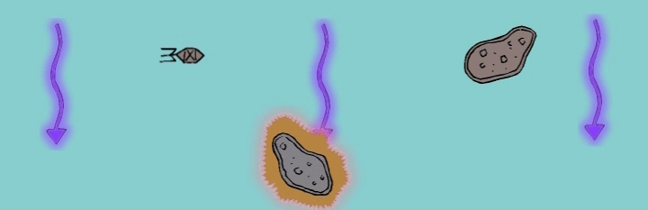
UV disinfection has become popular because it is very effective at inactivating protozoa, which can be resistant to a number of other disinfectants, such as chlorine. UV disinfection can qualify for up to 3 log credits under the Drinking-water Standards, depending on the dose. Also, compared to many other protozoa disinfection methods, UV is fairly inexpensive and requires relatively little maintenance or expertise.
Unlike chlorine, UV does not have an ongoing disinfection effect to prevent re‑contamination in the distribution system. As a result, UV is commonly used along with chlorination, because chlorine does have this residual effect.
UV light is generated by applying a voltage across a gas mixture, in the same way as happens in fluorescent lamps. There are a number of different types of UV lamp. The most common for small water supplies are low-pressure lamps. The name arises because the mercury vapour used to produce the light is at a low pressure inside the lamp. Medium-pressure systems are also used, particularly for large drinking-water supplies.
2.2 When should UV be used?
Choosing a treatment process depends on a number of variables, including the raw water quality, the budget and the final water quality required. Water suppliers should read Treatment Options for Small Supplies2 for an overview of the range of treatment options available.
Because effective disinfection depends on UV light reaching the target organism, anything that has a shading effect will prevent disinfection. This can occur when there are particles in the water, when the water is opaque to UV light, or because of ‘fouling’ on the lamp sleeves. It is for this reason that UV can only be used if the water has a low turbidity (less than 1 NTU)3 and high transmittance (over 80 percent). Sometimes pre-treatment will be needed so that the UV system can operate effectively (see section 2.4 for an explanation of these terms).
2.3 System design
The UV tubes are mounted in a stainless steel casing or ‘reactor’. The reactors should be located after any treatment processes that improve the clarity of the water (such as coagulation or filtration). They should also be placed before any processes that reduce the clarity of the water (such as lime dosing), because these will affect the transmittance of the water and hence reduce the effectiveness of the UV light.
UV can be used as a ‘point of entry’ treatment system for individual households. In this case the reactor needs to be large enough to treat the maximum flow for the household.
To comply with the Drinking-water Standards, a filter that reduces the water turbidity to less than 1 NTU must be installed prior to the UV reactor, unless the supply can demonstrate that the raw water turbidity is consistently less than 1 NTU. If this filter is a cartridge filter it must have a pore size no greater than 5 microns (nominal) and be a rigid cartridge (not pleated paper/fabric or string-wound).
Most UV reactors start up and shut down reasonably infrequently. A large number of on/off cycles will reduce the life of the UV lamps and may void the manufacturer’s guarantee (most manufacturers set a limit of three or four on/off cycles per day). This aspect of the operation of the UV reactor should be borne in mind when the location of the reactor in the water supply system is considered.
UV lamps can take a long time to start up because the lamps need to warm up before reaching full power. Start-up times range between one and ten minutes depending on the lamp type. Water suppliers need to take this into account, as any water that passes through the reactor before the lamp has warmed up will be untreated. Larger supplies may install an actuated valve (a valve that a motor will open or close) connected to a controller that tells the valve to open once the reactor has warmed up. This prevents untreated water from reaching customers.
The quartz sleeves covering the UV lamps will normally need cleaning. Often this is very infrequent and can be done manually by removing them and giving them a wipe down. A mechanised cleaning system can be used where frequent cleaning is expected (see section 2.4). These systems use wipers or a mechanism for filling and soaking the reactor interior in a chemical cleaning solution.
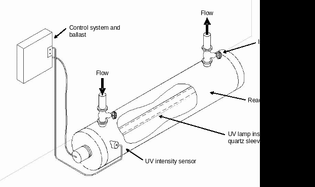
Figure 2: A typical small UV installation

Although some reactors can operate at high pressure, they can still be damaged by water hammer. (Water hammer is where the pressure in a pipe surges very quickly due to something like a valve opening or closing suddenly and can sound like a hammer blow on the pipe.) Particular care needs to be taken when opening and closing valves for this reason.
The water pressure lost across most UV reactors is quite small unless a flow restrictor is installed. In this case, the water supplier should do a hydraulic calculation to check that the system will function correctly.
UV reactors should be located in a building protected from the weather. The ballast system is a box full of electronic circuitry that regulates the current entering the lamp and converts the electricity to a more useful state. This ballast needs to be kept well ventilated because it will generate a considerable amount of heat. The lamps also generate heat, which can affect performance while there is no water flowing past to cool them. Some small systems include a bleed valve that releases the heated water to waste if the temperature reaches a particular level.
UV reactors should ideally be oriented so that the outlet is facing upwards to prevent air from becoming trapped inside. If the outlet is not facing upwards then an air purge valve should be installed on the top of the unit to enable the removal of any trapped air.
There should also be sufficient space to give access for maintenance. For example, a free space at least as long as the reactor is required so that the lamps can be removed.
UV reactors are very sensitive to power fluctuations. Generally this is not a problem, but loss of power can cause the lamp to lose its arc, which then takes time to re‑establish when power returns. The UV supplier should be consulted to ensure the power quality meets the requirements of the unit. If the site is very remote or experiences frequent power outages or fluctuations in voltage (this will be noticed as a sudden dimming of the lights), this information should be provided to the UV supplier. Power fluctuations can also shorten ballast life. There are ways around these issues, such as the use of an uninterruptible power supply (UPS).
Figure 3: UV system components
2.4 Water quality requirements
Because of the shielding effect the water can have, the effectiveness of UV disinfection is highly dependent on the quality of the water entering the reactor.
Another consideration is the rate of fouling (depositing of dirt/chemicals on the quartz sleeve inside the reactor). There are a number of chemicals that contribute to fouling, and these need to be tested for so that there are no surprises in terms of the level of maintenance required. These include hardness, iron and manganese.
There are specific minimum requirements listed in the Drinking-water Standards. Water quality results should be discussed with the UV supplier and an independent expert.
UV transmittance: UV transmittance is a measure of how much UV light is absorbed by chemicals and particles in the water and is normally given as a percentage transmittance through a 1 cm wide measuring cell at a light wavelength of 254 nanometres (nm). Transmittance is the most important consideration when choosing the size of the UV reactor. This means that it is important to know the UV transmittance of the water and how it varies before buying a UV unit. For example, a change in transmittance from 92 percent to 90 percent can result in the need for a 25 percent increase in reactor size.
Water with a transmittance below 80 percent cannot be treated with UV. Some forms of water treatment, such as coagulation/filtration, are effective at improving UV transmittance.
Turbidity: Turbidity is a measure of the cloudiness of water.4 It is usually quoted as a value in nephelometric turbidity units (NTUs). Turbidity of the water entering the UV unit should normally be less than 1 NTU and always less than 2 NTUs.
Turbidity and transmittance are similar in that they both measure how light passes through water. The difference is that transmittance measures the way the water absorbs the light, whereas turbidity measures the way the water scatters it.
Temperature: The output of UV lamps is affected by temperature. The optimal temperature for a low-pressure lamp is 40oC. A quartz sleeve around the lamp insulates it against low water temperatures. However, heat build-up at very low water flow rates can affect system performance.
Fouling: Compounds in the water can accumulate as ‘fouling’ on the lamp sleeves and other wet components such as the monitoring window of the UV sensor. Fouling reduces the amount of light available for disinfection. It is very hard to predict the rate at which fouling will accumulate, but the following compounds can cause problems.
A high level of hardness leads to the deposition of calcium carbonate (CaCO3) on the sleeves. Problems increase as the hardness increases. Levels above 200 mg/L (as CaCO3) may mean that water softening is needed for UV to be practical.
Iron and manganese can also precipitate onto the quartz sleeve. The cleaning frequency will increase with concentration. As a guide, concentrations above 0.2 mg/L of iron and 0.04 mg/L of manganese will mean relatively frequent cleaning is needed.
Samples to determine water quality should be taken from the point in the treatment process where the UV reactor will be installed. The samples need to be representative of the quality of the water that will be treated. As a guide, turbidity and UV transmittance could be measured weekly for one to two months if water quality is stable, or weekly for six to 12 months if the water quality changes a lot. Include samples where the water quality is likely to be at its worst, such as during poor weather, or when the turbidity is high (ie, after rainfall events).
2.4.1 Monitoring
For UV treatment to comply with the Drinking-water Standards, monitoring of certain parameters is required. The requirements vary according to the population served and are given in Table 2. The monitoring is designed to alert the water supplier when the system is not operating correctly, and to confirm that the system is operating to specifications.
In order to tell the operator when the unit is not working as intended, the UV intensity sensor must send an alarm to the operator if the intensity falls below the set point. This is required in order to comply with the Drinking-water Standards. It is also usual for the turbidity meter to send an alarm to the operator if the turbidity goes above the set point (usually 1 NTU), because this has the potential to cause non-compliance with the Drinking-water Standards.
Table 2: Drinking-water Standards requirements for monitoring
|
Population served* |
Requirements |
|
501–10,000 |
Continuous monitoring of flow, UV intensity and lamp outage on each reactor is required, along with continuous monitoring of combined turbidity. An alarm must be installed to notify the operator of the water supply when the flow or UV intensity falls outside the design limits, or if the turbidity exceeds 1 NTU. Samples must be taken to test the UV transmittance at least twice a week. If, after 12 months of monitoring, the transmittance has always been greater than 85% then the frequency can be reduced to once weekly. |
|
101–500 |
Continuous monitoring of UV intensity, lamp run hours, lamp outage and total flow is required. An alarm must be installed to notify the operator if the flow or UV intensity exceeds the design limits. Flow can be measured on each reactor or as a total over more than one reactor. If the total flow is measured, each reactor must have a flow restrictor fitted. This should limit the flow to within the ‘validated range’.5 Samples must be taken for turbidity and transmittance at least weekly for the first 24 months. If the transmittance does not fall below the design value during this period the frequency can be reduced according to the source type. If a supply takes water from a surface water source such as a river or lake, then monitoring can be reduced to monthly. If the supply extracts from a groundwater supply, then monitoring of transmittance can stop. |
|
100 or fewer |
Continuous monitoring of UV intensity, lamp run hours and lamp outage is required for supplies serving 100 people or fewer. Flow does not need to be monitored, but flow restrictors should be fitted to each reactor to limit flow to within the validated range for the reactor. An alarm should be installed to notify the operator if the UV intensity exceeds the design limits. Any additional requirements specified in the certification must be adopted as well. UV transmittance and turbidity should be sampled manually at least once a month. |
* This booklet is targeted at water supplies serving up to 5000 people, so supplies serving over 10,000 people are not included.
2.5 Certification of UV disinfection systems
For a UV reactor to comply with the Drinking-water Standards it must have appropriate certification. Certification is proof that a particular reactor model gives sufficient disinfection at a certain UV transmittance and flow. Under the Drinking-water Standards, approved certifiers are NSF, DVGW and ÖNORM.
Depending on the standard used for certification, operators should check the following details for any reactor under consideration.
NSF-ANSI-55 Class A: UV units that meet the NSF standard are listed on the following website: http://nsf.com/Certified/DWTU/. Operators should refer to the NSF website and check that the UV brand and model are listed (meaning that it has been tested and approved). Scroll down the page to ‘Reduction Claims for Ultraviolet Microbiological Water Treatment Systems’. Click on the box ‘Disinfection Performance, Class A’. This brings up a list of the brands and models that have been tested and approved. Always check the website electronically: do not rely on printed versions.
DVGW Technical Standard W294: UV units that meet the DVGW standard are issued with a certificate, and each unit carries a name plate. The operator must ask to see the original DVGW approval certificate. This is contained within the equipment’s instruction book. Be aware that a performance graph on its own does not constitute an approval certificate.
ÖNORM M5873-1 Standard: UV units that meet this Austrian standard are issued with validation documentation that includes a graph indicating acceptable flow rates dependent on the UV Transmittance (UVT) of the filtered water and UV intensity. Operators should check that the reactor under consideration is certified to treat the flow and transmittance characteristics of the supply.
2.6 Operating a UV system
Operating a UV system is fairly straightforward. The guidelines that follow are general and particular UV systems will have their own maintenance requirements. Table 3 gives an outline of the routine maintenance needed on UV reactors. The frequency and activities required will vary depending on what is installed and the water being treated.
Table 3: Routine maintenance tasks
|
Task |
Action |
Indicative frequency |
|
Check for fouling on sleeves |
If fouling is observed on the sleeves, clean the sleeves and sensor windows. Sleeve fouling can be difficult to see. Try placing the sleeves on a clean, white, lint-free cloth next to a new sleeve for comparison. Cleaning should be according to the manufacturer’s instructions. Care should be taken to use cleaning chemicals that will not scratch the lamp sleeve; examples include Lime Away and CLR. The inside of the lamp sleeve should be dried before reinstallation. One way to do this is with isopropyl alcohol and a lint-free cloth. Be careful when fitting quartz sleeves because it is easy to break them by over-tightening the compression nuts. Wiper systems and manual cleaning of the quartz sleeve can cause scratching, which results in reduced transmittance of the UV light, reducing the system’s effectiveness. Replace sleeves if damage, cracks or irreversible fouling is observed. While the reactor is drained for the sleeve inspection, the inside should be inspected and cleaned if necessary. |
Monthly; adjust frequency based on fouling rate. |
|
Check UV intensity sensor |
Compare the reading of the duty UV intensity sensor to that of the reference sensor. |
Monthly |
|
Check UV reference sensor calibration |
For supplies serving fewer than 500 people this can be done against another water supplier’s reference sensor. Supplies serving over 500 people will need to send the sensor to an appropriate facility, or after 12 months replace the duty sensor with the reference sensor and purchase a new reference sensor. |
Annually |
|
Test trip ground fault circuit breakers |
Test the ground fault circuit breakers in accordance with the manufacturer’s recommendations. They usually last for about a year of constant use. |
Annually |
|
Replace lamps |
Lamps are normally replaced based on the number of hours run. See the manufacturer’s specifications. |
Approximately annually |
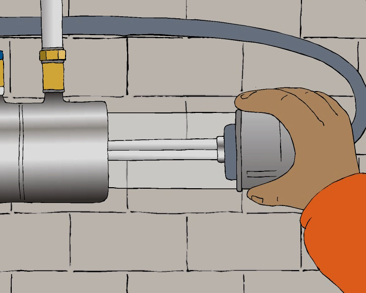
Cleaning and inspection of the quartz sleeve and UV sensor should be undertaken by a suitably qualified person. It is best left to a supplier or supplier’s agent.
Figure 4: The quartz sleeve should be inspected regularly for fouling
2.6.1 Lamp replacement
Lamp output decreases over time, so lamps must be replaced periodically to maintain a sufficient UV dose. Lamps are normally replaced based on the manufacturer’s instructions. All of the lamps in a reactor are generally replaced at the same time unless a lamp fails. Only replace with lamps supplied by the manufacturer, otherwise reactor certification becomes invalid.
Lamps should be handled in accordance with the manufacturer’s instructions using clean cotton, powder-free latex or vinyl gloves. Fingerprints can interfere with their proper operation.
When replacing lamps, they should not be inserted so that they will affect the reading of the UV intensity sensor. Note that the wire that runs along the lamp can cast a shadow that can cause a falsely low UV intensity reading.
UV lamps are commonly disposed of in landfills. However, environmental best practice is to recycle the tubes to recover the mercury, which is a hazardous substance. Some UV suppliers and councils will accept spent tubes, or they can be sent direct to the recyclers. Recycling costs approximately $1 per tube (as of 2007).
2.6.2 Sleeve replacement
The sleeves should be replaced when they are damaged, or when permanent staining reduces UV intensity to an unacceptable level. Because the sleeves are fragile, water that causes a lot of fouling will increase the frequency of sleeve replacement due to permanent deterioration.
Sleeves should be handled in accordance with the manufacturer’s instructions using clean cotton, powder-free latex or vinyl gloves to avoid leaving fingerprints on the surface.
2.6.3 Spare parts
Components inevitably wear out or break. Spare parts are used to repair faults quickly after they happen. What parts need to be kept and in what number will depend on how quickly replacement parts can be obtained and how long the water supply can make do with a unit out of service. The following spare parts might be kept in storage: lamps, sleeves, O-ring seals, ballast, ballast cooling fan, UV intensity sensor.
The following table gives an indication of the typical operating life of the main components of a UV reactor. The figures are typical and will vary between manufacturers and with advances in technology. They will also vary with the specific characteristics of the water supply, such as how the system is operated and the quality of the power supply.
Table 4: Typical operating life for various components
|
Component |
Typical operating life |
|
Low-pressure lamp |
12,000 hours |
|
Medium-pressure lamps |
8,000 hours |
|
Duty and reference sensor |
3–10 years |
|
Electronic ballast |
10–15 years |
See the comments in section 2.6.1 about lamp replacements and the manufacturer’s requirements.
2.6.4 UV intensity sensor calibration
See the equipment supplier for advice on sensor calibration.
2.6.5 Start-up following maintenance
After maintenance, the operator should watch the initial start-up to ensure everything has been put back together properly. The operator should check the following during start-up:
all lamps are operating and the UV intensity sensor is reading the expected value (or is not registering an alarm)
there is no build-up of heat on the top of the reactor after it has been running for a while (this would indicate that an air pocket may remain in the vessel).
2.7 Troubleshooting
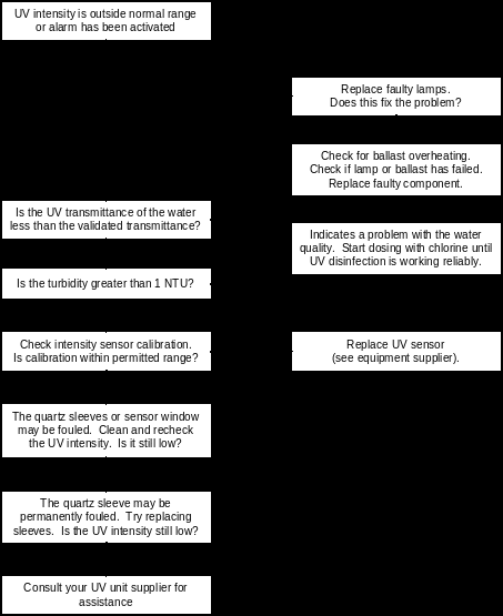
A number of things can prevent the reactor treating the water effectively. The UV intensity sensor warns of many of the problems that affect the safety of the water. All supplies must monitor the intensity continuously and have an alarm installed to alert the operator if the value drops too low.
Low intensity can be caused by
high water turbidity
water contamination, leading to low UV transmittance
excessive fouling of the quartz sleeve or sensor window
lamp or ballast failure
drift in the UV intensity meter calibration (it tends to drift downwards).
Figure 5 can be used to help determine the cause of the low intensity.
Figure 5: Low UV intensity troubleshooting
3 Cartridge Filtration
3.1 Cartridge filter principles
Cartridge filters remove particles from the water as it passes through a porous medium. Particles larger than the pores in the filter are trapped on the outside and the smaller particles pass through, just like a tea strainer.
Cartridge filters can be an effective way of removing turbidity and protozoa from water. They will not remove bacteria and viruses, because these are smaller than the pore sizes available. In addition, simple filtration will not remove dissolved contaminants such as colour or dissolved metals. These would need to be removed by a different process, such as reverse osmosis, or micro, nano and ultra filtration.
Certified cartridge filtration can qualify for 2 log Cryptosporidium removal credits under the Drinking-water Standards, or 0.5 log credits if preceded by another form of approved filtration.
A cartridge filter consists of one or more filter cartridges, which slot into a housing. Cartridges can be made of a rigid or flexible material. They have to be thrown away when they become blocked. Cartridge filters are well suited to small water supplies because they are simple, inexpensive, require minimal maintenance and cope reasonably well with varying water quality. However, the incoming water quality needs to be low in turbidity, otherwise filter replacement becomes very frequent and expensive.
Five micron cartridge filtration is often used to pre-treat water prior to UV treatment so that the water is sufficiently clear for the UV light to pass through (see section 2.3 of the Drinking-water Standards).
|
|
|
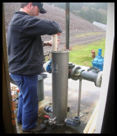
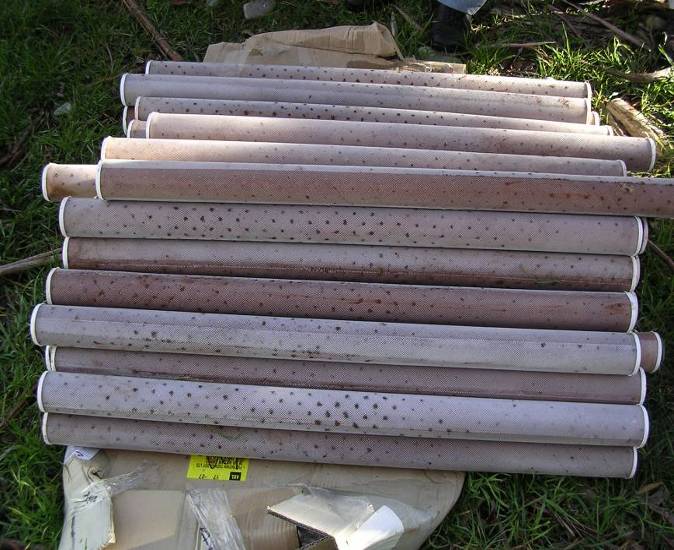
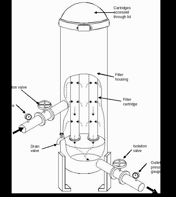
Figure 8: Cartridge filter components
3.2 Cartridge filter system components
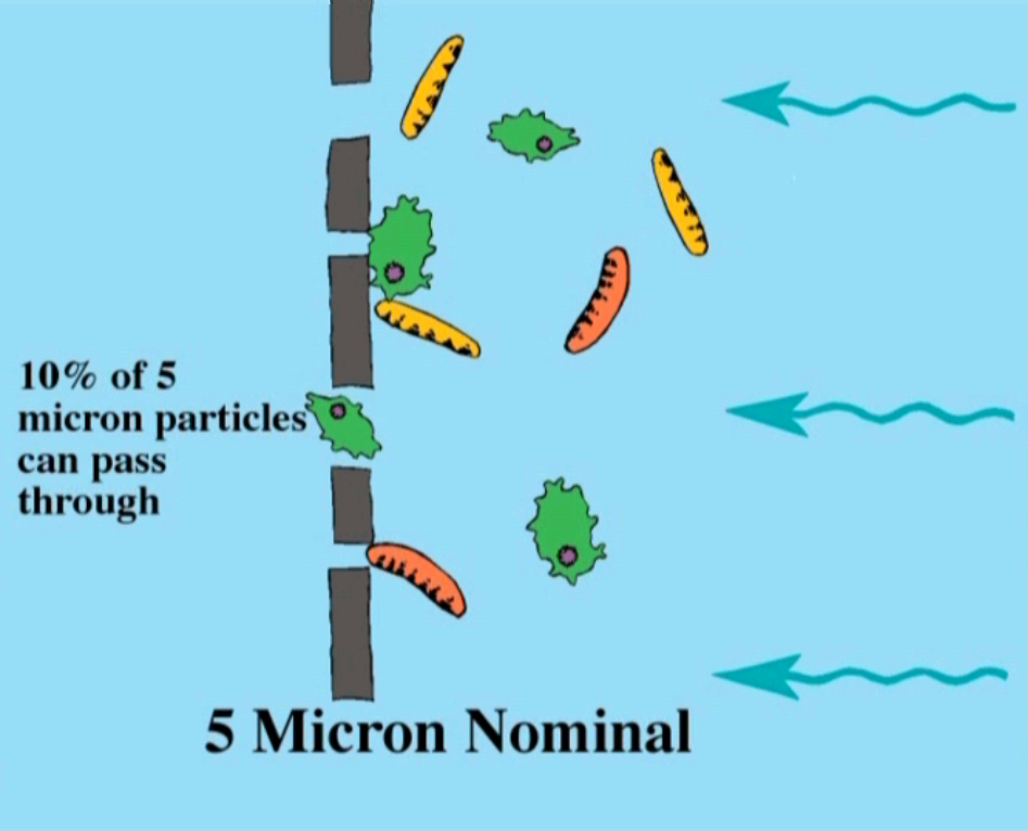
The cartridges used in cartridge filters consist of a rigid core (usually polyvinyl chloride – PVC) surrounded by a filter medium. Examples of filter media are wound polypropylene and pleated polyester. Filters are available in a range of pore sizes but are typically sold in 100, 50, 25, 10, 5 and 1 micron (µm) sizes. Pore sizes can be absolute or nominal. Absolute means that all pores are the size specified or smaller. Nominal means the specified pore size is the average, so some larger particles will still pass through.
Figure 9: Nominal versus absolute pore size
|
|
|

The effectiveness of treatment obviously depends on the size of the particles in the water.
When using cartridge filters to remove turbidity, the pore size will normally be chosen based on trial and error. Sometimes the particles in the water that cause the turbidity are too small to be removed effectively by cartridge filters. The different types of soil particle are given in Table 5.
Table 5: Sizes of different soil particles
|
Clay |
< 2 micron (ie, 0.002 mm) |
|
Silt |
2–20 microns |
|
Fine sand |
20–200 microns |
Protozoa vary in size between 3 and 9 microns. Because protozoa can deform as they pass through a filter, a 1 micron cartridge filter certified for 3 log Cryptosporidium removal is required for effective removal (see section 5.12.1 of the Drinking-water Standards). To increase the useful life of a 1 micron cartridge filter, it is common to pre-treat the water with a coarser cartridge. The best pore size of the pre-treatment cartridge should be determined by experimentation, but a cheaper cartridge with a larger nominal pore size is normally used.
Figure 1: Coarse pre-treatment cartridge filter mounted before a fine cartridge filter

Housings for large cartridge filters are generally made of stainless steel. Smaller housings are made of either stainless steel or plastic. Housings can contain between one and twenty filter cartridges. Most housings are opened from the top with a lid, which is sealed with an O-ring and clamped, bolted or screwed in place.
3.3 Monitoring
Certain monitoring requirements have been included in the Drinking-water Standards. These are designed to demonstrate compliance and alert the water supplier if the system is not operating correctly. The key parameters are differential pressure, flow and turbidity.
|
Pressure differential |
Pressure differential is the difference in pressure across the filter, otherwise called the ‘head loss’ across the filter. This is normally measured by taking the water pressure at the filter inlet and subtracting the water pressure at the filter outlet. The pressure differential will gradually increase as the filter blocks. The cartridge will require replacing when the differential pressure exceeds the manufacturer’s recommended level (as a rule, a 1 bar difference between the inlet and the outlet). If the pressure differential drops below the last recorded value then the filter may have burst, or it may have ‘unloaded’ some of the particles it had collected. If this occurs it must be assumed that the cartridge has failed. |
|
Flow |
It is useful to keep records of the flow that has passed through a filter to get a feel for how long a cartridge will last and when it may need replacing. |
|
Turbidity |
Treated water turbidity indicates how well the filter is removing material in the target range. This should be less than 0.5 NTUs. |
Table 6: Drinking-water Standards minimum requirements for monitoring
|
Population served* |
Differential pressure |
Flow |
Turbidity |
|
501–10,000 |
Continuous measurement on each housing |
Continuous measurement |
Minimum of one turbidity meter for every filter (or housing), or daily manual sampling |
|
500 or less |
Weekly readings |
Daily readings (can use a simple water meter) |
Not required (but recommended in order to detect filter failure). |
* This booklet is targeted at water supplies serving up to 5000 people, so water supplies serving over 10,000 people are not included.
3.4 Operating a cartridge filter system
Cartridge filters must be routinely checked and periodically replaced. Only use filter cartridges approved for use in the assembly or filter housing. The date on which a new cartridge is installed should be recorded so that its length of service and the volume treated can be checked. Filtering to waste for the first five minutes after any maintenance is recommended to allow the filtration process to settle down.
The following checklist may be useful when changing a cartridge.
3.4.1 Cartridge filter servicing checklist
Filter housing, filter housing seal and cartridge seal checked for problems or leaks.
Filter housing wiped clean and disinfected before installation or after any maintenance
Correct filter cartridge used for the particular housing.
Cartridge is located correctly in the filter head and housing.
Seals replaced and lubricated in accordance with the filter manufacturer’s recommendations.
Filter housing is replaced and tightened correctly.
Flow flushed to waste before putting the filter back into service.
System checked for leaks.
Head loss, date of work and work done, including date of cartridge change, recorded and head loss checked to make sure it is within the correct range.
3.5 Troubleshooting
One of the attractions of cartridge filters is their simplicity. Nevertheless, problems can sometimes develop. Table 7 gives guidance on common problems.
Table 7: Troubleshooting guide for cartridge filtration
|
Indicator |
Possible problem |
Solution |
|
Rapid increase in head loss and short filter lifespan |
Incoming water too dirty |
Install or improve pre-treatment. Consider installing a coarse cartridge filter upstream. |
|
One filter blocks much earlier than the others |
Uneven flows to individual filters |
Improve control of flows to individual filters. |
|
Spikes in filtered water turbidity during a filter run |
Sudden changes in flow rate to a filter are causing it to ‘unload’, particularly where high pressures are allowed to build up |
Look for causes of sudden changes in flow to the filters. Use slow operating valves to control flow to the cartridges. Some valves are opened by the 90 degree turn of a handle. As a result the flow can go from zero to full flow very quickly. Valves that require many turns of a handle to open them are preferable. |
|
Flow declining and possible increase in treated water turbidity |
Changing cartridges too late |
Is the pressure differential or treated volume being checked regularly enough? |
|
High filtered water turbidity |
Cartridge pore size is too large |
Investigate reducing the cartridge pore size or changing from a nominal size to an absolute size. Of course, if more material is removed then the cartridge will have to be replaced more often. It may not be practical to remove very fine sediment with cartridges. |
|
Cartridge not seated or installed correctly |
||
|
Cartridge is starting to unload |
Replace cartridge. Take a note of the pressure differential. Has it been allowed to increase too high? |
|
|
Cartridge has ruptured (sudden loss in differential pressure) |
Replace cartridge. Is the upstream pressure too high? Was the cartridge damaged before installation? |
|
|
Heterotrophic plate count increases across filter |
By concentrating particles in one area, cartridge filters can contribute to the growth of non-coliform bacteria |
Difficult to prevent but can minimise with frequent cleaning, cartridge replacement and post-chlorination. |
1Drinking-water Standards for New Zealand 2005 (revised 2008).
2Ministry of Health Resources for Drinking-water Assistance Programme.
3NTU = nephelometric turbidity unit.
4More specifically, turbidity is a measure of the scattering of light by particles in the water.
5The ‘validated range’ is the flow range over which the reactor has been tested and certified to ensure there is sufficient disinfection at a given transmittance. See section 2.6 for more details on reactor certification.
UV DISINFECTION AND CARTRIDGE FILTRATION RESOURCES FOR DRINKINGWATER ASSISTANCE
Tags: assistance programme, drinking-water assistance, resources, filtration, cartridge, disinfection, drinkingwater, assistance
- AUTOR MARKO PUHALOVIĆ BRAINWAVE RELAKSACIJA KORISNIKA SEMINARSKI RAD
- 8TH BASIC CONCEPT IN INFECTION CONTROL (EXCERPT OF EPIDEMIOLOGY
- FEDERAL PROCUREMENT DATA SYSTEM – NEXT GENERATION (FPDSNG) WEB
- CINCO SUTTAS BÁSICOS DEL BUDISMO I1 EL PRIMER DISCURSO
- KOMISJA GENETYKI SĄDOWEJ PTSMIK ZASADY ATESTACJI LABORATORIÓW GENETYCZNYCH
- OFFALY COUNTY COUNCIL DIFFERENTIAL RENT SCHEME 2010 HOUSING (MISCELLANEOUS
- ORAL ENTERAL NUTRITION PRODUCTS FOR CLIENTS 20 YEARS OF
- VODOVOD I KANALIZACIJA DOO HERCEGOVAČKA 8 21000 SPLIT TELEFONCENTRALA
- SGGS COLLEGE SECTOR 26 CHANDIGARH COLLEGE SPORTS POLICY DEPARTMENT
- PRIPORT JP 5000 WSZECHSTRONNE URZĄDZENIE FORMATU A3 P OWIELACZ
- UNIVERSIDAD AUTÓNOMA DEL ESTADO DE MÉXICO UNIVERSIDAD JAUME I
- SUPPLEMENTAL HOŁUBIEC COUPLETURN SOURCES II SOURCES REMARKS OBSERVATIONS ANECDOTES
- ZAŁĄCZNIK DO UCHWAŁY NR LI5312010 RADY MIEJSKIEJ W MŁAWIE
- ES IMPORTANTE MENCIONAR QUE NO SE DARÁ CURSO A
- BSA IMPERIAL WHARF MEETING ROOM BOOKING PROCEDURE 1 CONTACT
- SKRIFTLIG FORESPØRGSEL E468508 AF CHRISTEL SCHALDEMOSE (PSE) TIL KOMMISSIONEN
- INMUNOQUÍMICA PREGUNTAS Nº 1 TIPO A DIFICULTAD 1
- LA LIBERTAD GUIANDO AL PUEBLO DELACROIX FICHA TÉCNICA
- 2 PATVIRTINTA JAUNIMO REIKALŲ DEPARTAMENTO PRIE SOCIALINĖS APSAUGOS IR
- PUBLICADO EN LA GACETA OFICIAL DEL DISTRITO FEDERALEL 25
- AD HOC RESULTS POSTINGGENERATIONREFRESH REQUEST FORM RPO ASU OFFICE
- GROUP 7 NAZWA PRZEDMIOTU JEDNOSTKA PROWADZĄCA PRZEDMIOT FILIA UMFC
- INTRODUCTION TO OCCUPATION PREPARING FOR STUDYING OCCUPATIONAL THERAPY INTRODUCTION
- TEST YOURSELF ON HARVARD REFERENCING QUIZ INSTRUCTIONS
- III SEMINARIO DE COOPERACIÓN Y DESARROLLO EN ESPACIOS RURALES
- I PRIEDAS DAILIOJO JOJIMO RUNGTYS 11 LIETUVOS ŽIRGINIO SPORTO
- WORSHIP ON THE…BASS GUITAR – CHAPTER 3 WE’VE LEARNED
- ENERGY NÁVRH TUREK NÁVRH HRUBÝ VĚK ENERGIE MJ ENERGIE
- CURRICULUM VITAE CRAIG T JORDAN PHD 1 BIOGRAPHICAL SKETCH
- DRAFT DOCUMENT RETROSPECTIVE PERFORMANCE ASSESSMENT OF THE TEST GUIDELINE
THE SONATAS OF DOMENICO SCARLATTI ON MIDI DOMENICO SCARLATTI
PSCEDFSATISD MODERATOR CHRISTAL SIMMS 1108171200 PM CT CONFIRMATION
TANIMLAR VE TEMEL KAVRAMLAR KALITE ÖZELLIKLE ÇEVREMIZDEKI TÜKETIM MALLARI
UNDER THE WATERFALL ‘WHENEVER I PLUNGE MY ARM LIKE
101107 GESTION DES BIENS PUBLICS AU NIGER LA TRANSPARENCE
EXERCICIS UNITAT 3 MESCLES I SOLUCIONS QUÍMICA 1
 FACILITY DISCHARGE SUMMARY ORIGINAL TO BE GIVEN TO RESIDENT
DECALOGO DE CONDUCTA Y ETICA SINDICAL 1 MANTENER UNA
WHEN SAVING THIS FILE FROM
not Here any More the Address is now
 LIC FELLMAN MENDEZ RAMALLO MEDIOS DE PAGO EN EL
DATA WPŁYWU DO BIBLIOTEKI NARODOWEJ PIECZĘĆ INSTYTUCJI ZAŁĄCZNIK NR
NA TEMELJU ČLANKA 391 STAVKA 1 ZAKONA O VLASNIŠTVU
 JORNADA SOBRE EL TACÓGRAFO DIGITAL DÍA 28 DE JULIO
 13august 19august 2007 33uge Hvid Mandag 13august
INSTRUCCIONES PARA ESTUDIAR Y HACER EL EXAMEN DE METABOLISMO
HARDSHIP OR EXTENUATING CIRCUMSTANCES WITHDRAWAL WHAT DO I DO
LEY DE INGRESOS DEL ESTADO DE NUEVO LEÓN PARA
 VI ESTUDIO DEL LENGUAJE 1 LENGUAJE LENGUA Y HABLA
 16 FISIOPATOLOGÍA TRASTORNOS DEL METABOLISMO HIDROELECTROLÍTICO TRASTORNOS DEL METABOLISMO
