FIG3 RPA PARALLEL CONNECTED LOAD CONNECTED BY AUXILIARY RELAY
1 CS451 INTRODUCTION TO PARALLEL AND DISTRIBUTED COMPUTING12252021 REV C SECTION 16XXX PARALLELING SWITCHGEAR SPECIFICATION MEDIUM
A RELIABLE ARCHITECTURE FOR PARALLEL IMPLEMENTATIONS OF THE ADVANCED
A USSCHREIBUNGSTEXT ZENTRALBATTERIELEUCHTE RCG DESIGN RETTUNGSZEICHENLEUCHTE FÜR PARALLELE WANDMONTAGE
ALLEGATO ALLE PROGRAMMAZIONI INDIVIDUALI PER DIPARTIMENTICLASSI PARALLELE A RISULTATI
ALPHASORT A CACHESENSITIVE PARALLEL EXTERNAL SORT CHRIS NYBERG TOM
upute za upotrebu BCR2400
|
|
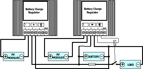
Fig.3. RPA parallel connected, load connected by auxiliary relay (PV-field power and load consumption are higher then that of regulator)
4. TROUBLE SHOOTING
4.1. Load supply control
If red LED "OUTPUT" is off, disconnect load and after that disconnect and reconnect battery.
If now LED comes on, load was disconnected owing to battery deep discharge. If LED still stays off, measure the battery voltage. If the battery voltage is higher than 12 V, replace the regulator.
4.2. Charging process control
If the regulator always stays in shunt mode (charge led off), measure the battery voltage. If it is lower than 13 V replace the regulator.
When the regulator always stays in charge mode (charge led on) and battery voltage is higher than 15V replace the regulator. For battery voltages lower than 15V compare battery and PV field voltages. Voltage is different by not more than 1V. In the other case regulator or wiring are faulty.
A D R I A T I C B. B.
HR - 21000 Split, Istarska 13
tel. (+38521) 345 193, fax. (+38521) 360 649
BATTERY CHARGE REGULATOR
RPA-8 12V/8A
RPA-8 24V/8A
Installation and operation manual
Congratulations, you have now joined satisfied ADRIATIC clients around the world. They depend on our solar systems each day with confidence.
We recommended you thoroughly read this manual before commencing installation
Technical characteristics
|
TYPE |
RPA-8 12V/8A |
RPA-8 24V/8A |
RPA-10 12V/10A |
|
RPA-10 12V/10A |
|
RATED VOLTAGE |
12 V |
24 V |
24 V |
|
24 V |
|
MAX. P.V. FIELD VOLTAGE |
24 V |
48 V |
48 V |
|
48 V |
|
OVERCHARGE VOLTAGE LIMIT* |
14,2V |
28,4V |
28,4 V |
|
28,4 V |
|
DISCHARGE VOLTAGE LIMIT* |
10,8 V |
21,6 V |
21,6 V |
|
21,6 V |
|
MAX. P.V. FIELD CURRENT |
8 A |
8 A |
2 A |
|
2 A |
|
RATED LOAD CURRENT |
8 A |
8 A |
2 A |
|
2 A |
|
SELF CONSUMPTION |
5 mA |
5 mA |
5 mA |
|
5 mA |
|
OPERATING TEMPERATURE |
-15 do 50 oC |
-15 do 50 oC |
-15 do 50 oC |
|
-15 do 50 oC |
|
STORAGE TEMPERATURE |
-50 do 80 oC |
-50 do 80 oC |
-50 do 80 oC |
|
-50 do 80 oC |
|
DIMENSIONS |
70 x 50 x 32 mm |
70 x 50 x 32 mm |
70 x 50 x 25 mm |
|
70 x 50 x 25 mm |
|
WEIGHT |
0,11 kg |
0,11 kg |
0,08 kg |
|
0,08 kg |
* other adjusted values factory option only.
1. GENERAL OPERATION
RPA is efficient, compact, water proof and solid state regulator used for controlling battery charging by P.V. modules. Its circuitry is fully solid-state and uses a low-frequency PWM switching shunt technique to control battery voltage which does not generate RFI. Do not use the regulator to regulate a power source other than a Photovoltaic module. Following features are obtained:
- Prevent discharging batteries by P.V. modules at night.
- Overcharging and deep discharging protection.
- Increase efficiency in conversion of solar energy.
- Decrease degradation phenomena when applied at amorphous silicon modules.
- Extended battery life time.
- Reduces system maintenance.
- OPTION:Electronic short-circuit and overload protection with reset.
When the regulator is in the charge mode, LED "charge" is lighting. As battery charges, battery voltage will rise slowly until it reaches the overcharge voltage limit. At this point overcharge protection connect PV modules in short circuit condition when no power is produced by the array and battery charging stops. "Charge" LED goes out. When the battery voltage drops to the charge resumption level, the regulator will connect PV modules to the battery again and charging will resume. At full charge, the regulator will pulse current into the battery to achieve and maintain full charge. This pulse charging is indicated by occasional blinking of the "charge" LED.
RPA has deep discharge protection. It disconnect the load before the battery voltage goes too low, to prevent deep discharge damage to batteries. When LED "output" is off, it indicates activation of deep discharge protection. After a certain amount of recharge, the protection resets and load is switch on again (red LED "output" goes on). It can be reset manually before recharging by temporary connecting terminals No. 7 (RESET) and No. 6 (-) on models with reset terminal.
In the case of short circuit or overload, electronic protection disconnect load. After repairing, reconnect load by temporary connecting terminals No. 7 (RESET) and No. 6 (-). ( On models with reset terminal ONLY )
2. INSTALLATION
RPA should not be placed on surface which is subjected to direct sunlight or heated in excess of 45 oC. Regulator has to be placed within 1 meter of the battery, and fix to vertical plane surface with athesive tape.
3. WIRING
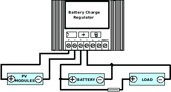
After mounting, complete the wiring to the rest of the system. Refer to Fig. 1, Fig. 2, or Fig. 3.
Use wires of adequate cross-section (1 mm2 is recommended)
Pay attention to the correct polarity. Connect the battery terminals first then PV-Modules and load last. It is recommended to use 8A fuse for load protection.
If battery is disconnected while load and P.V. modules are connected to regulator, voltage higher than 14V could be passed to load and destroyed some sensitive loads. To prevent that always connect battery first and disconnect it last. For most systems connect regulator according to Fig. 1. When discharge protection has to be eliminated, use Fig. 2. For loads heavier than rated, use a relay as a load disconnecting device, refer to fig. 3. For PV-fields larger than rated, regulators can be wired in parallel to sub-arrays (fig.3).
Don't connect regulator to PV-field with higher max. voltages then those mentioned in technical data.
|
|
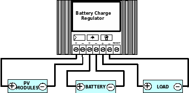
Fig.1. Load directly connected to regulator (load consumption lower than regulator nominal output power)
|
|
|
Fig.2. Load directly connected to battery (discharge protection off) |
ANHANG B 4 BESCHLEUNIGTE BEZUGSSYSTEME B 41 PARALLELVERSCHIEBUNG GEGEN
ÅLANDS LANDSKAPSSTYRELSE PARALLELLTEXTER DATUM 20011108 PARALLELLTEXTER TILL LANDSKAPSSTYRELSENS FRAMSTÄLLNING
CAPSL COMPUTER ARCHITECTURE AND PARALLEL SYSTEMS LABORATORY DEPARTMENT OF
Tags: connected by, directly connected, connected, relay, auxiliary, parallel
- COMISIÓN DE MATERIA PARA LA PRUEBA DE ACCESO A
- 0 COMUNIDAD ANDINA SECRETARIA GENERAL SGDI 150
- 10 „FASZINATION KIRCHENGESCHICHTE“ PETER F BARTON UND „SEIN“
- TOOL FOR ASSESSMENT OF SUICIDE RISK (TASR) NAME
- CALVIN VINCENT LISTA DE UTILES ESCOLARES DE PREK 2019
- ESTT OEP 2013 GRUPO DE MATERIAS COMUNES DE
- EL CONSELL APRUEBA LA CREACIÓN DE CUATRO ESCUELAS MUNICIPALES
- COMUNICATO STAMPA TORNANO IN PISTA LE FLOTTE AZIENDALI CON
- ADATVÉDELMI TÁJÉKOZTATÓ BAKONYI ERŐMŰ ZÁRTKÖRŰEN MŰKÖDŐ RÉSZVÉNYTÁRSASÁG ÜGYFÉLSZOLGÁLAT AZ
- POPSICLE STICK TRUSS BRIDGE INSTRUCTIONS AND PHOTOS STEP 1
- le web au Liban Statistiques et Meilleurs Sites
- NEVADA PHYSICAL THERAPY BOARD 7570 NORMAN ROCKWELL LANE SUITE
- REPRESENTED ABOVE ARE FIVE IDENTICAL BALLOONS EACH FILLED TO
- QUESTIONS REGARDING THIS MOA? PLEASE CONTACT ? 7827??? SAN
- VFT045 FASTIGHETSEKONOMI HT 2008 ÖVNING 20080909 1 KASSAFLÖDESMETOD I
- RENCANA STRATEGIS (RENSTRA) PROGRAM STUDI S1 TEKNIK INFORMATIKA UNIVERSITAS
- CALL FORINDEE+POSTDOCTORAL FELLOWSHIP (IPDF) INTERESTED RESEARCHERS CAN SUBMIT THEIR
- HOW CHILD SUPPORT IS CALCULATED (AND OTHER FREQUENTLY ASKED
- PERFIL PROFESIONAL DEL PROTÉSICO DENTAL 1 EL PROTÉSICO DENTAL
- PROGRAMA DE FIESTAS VIRGEN DEL CARMEN EL CAMPELLO 2009
- GRUPA 3 ZAŁĄCZNIK NR 2 NUMER PROCEDURY ZKPOWR12017 OŚWIADCZENIE
- SCHOOL DISTRICT NAME SCHOOL DISTRICT ADDRESS SCHOOL DISTRICT CONTACT
- ОДАБРАНИ И НАГРАЂЕНИ РАДОВИ НАГРАДНОГ КОНКУРСА ЗА ИДЕЈНО РЕШЕЊЕ
- 2 82012 (X 26) FVB FŐVÁROSI VÁLASZTÁSI BIZOTTSÁG 1052
- QUÍMICA 2º BACHILLERATAO CINÉTICA EQUILIBRIO Y ACIDOBASE 1) SE
- CLOWN (BÁSICO) DEL 22 DE AGOSTO AL 10 DE
- PRODROP AND PRONOMINAL SUBJECTS REANALYZING FEATURES IN THE HISTORY
- PROJECT NAME RISK MANAGEMENT PLAN TEMPLATE VERSION 11 DRAFT
- APPEL D’OFFRE MONITORING DANS LES MICI IBD MONITORING
- PRUEBA DE HABILIDAD PARA SEGUIR INSTRUCCIONES 1 LEE TODAS
PROPOSED ETHANOL OFFLOADING FACILITY AT NORFOLKSOUTHERN RAIL YARD INTRODUCTION
19 SUBGRAM DAILY SUPPLEMENTATION WITH DOCOSAHEXAENOIC ACID PROTECTS LOWDENSITY
 REGLAMENTO DE ESTÍMULOS ECONÓMICOS AL MÉRITO DEL CENTRO DE
 ASAMBLEA GENERAL ORDINARIA Y ELECCIÓN DE AUTORIDADES CONVOCATORIA A
CÁC HẠNG MỤC ƯU TIÊN TRONG CHƯƠNG TRÌNH “VIỆN
 COMPROMÍS DE CONTRACTACIÓ DE LA PARTICIPANT PER PART DE
SPÄŤ NA ÚVODNÚ STRÁNKU ZOZNAMU ABSOLVENTOV (KLIKOM SA VRÁTI
REGIONAL UTILIZATION RESOURCE REVIEW INDIVIDUAL REVIEWED DATE REVIEWED
 SOLICITUD ALOJAMIENTO EN FAMILIA FAMILY STAY APPLICATION FORM
 3GPP TS 32299 V13340 (201520161203) TECHNICAL SPECIFICATION 3RD GENERATION
TARIFAS CENTRO DE PRODUCCIÓN AUDIOVISUAL 2013 DESCRIPCIÓN CARÁCTERÍSTICAS VALOR
ZAŁĄCZNIK 1 DNIA (PIECZĘĆ WYKONAWCY) OFERTA
STRATEGIC AND CRITICAL THINKING REX C MITCHELL PHD “CRITICAL
 A CHANGE IN THE SCENERY CURRENT SITUATION MANY FOLKS
TEMELJEM ČLANKA 6 ZAKONA O SAVJETIMA MLADIH ( NN
 BELL SCHEDULE THE BELLS SIGNIFY THE BEGINNING AND END
 SADRŽAJ POZIV ZA SUDJELOVANJE WELCOME MESSAGE VAŽNE ADRESE
MINUTES OF THE LIBRARY ADVISORY BOARD MEETING MONDAY OCTOBER
 CAPTIVE CARE GRANT GUIDANCE NOTES THE PRIMATE SOCIETY
ŠTEVILKA 00701420157 LJUBLJANA DNE 22052015 EVA 201519110002 GENERALNI SEKRETARIAT
