PROCEEDINGS OF THE IEEE INTERNATIONAL CONFERENCE ON ROBOTICS AND
1 VERBATIM PROCEEDINGS CONNECTICUT STEM CELL RESEARCH ADVISORY COMMITTEE161 ANAIS DO 47º CONGRESSO BRASILEIRO DE CERÂMICA PROCEEDINGS
1627 ANAIS DO 47º CONGRESSO BRASILEIRO DE CERÂMICA PROCEEDINGS
1741 ANAIS DO 47º CONGRESSO BRASILEIRO DE CERÂMICA PROCEEDINGS
2 SOLID STATE PHYSICS (INDIA) 45 (2002) XXXXXY PROCEEDINGS
2035 ANAIS DO 47º CONGRESSO BRASILEIRO DE CERÂMICA PROCEEDINGS
THE GUIDECANE C A COMPUTERIZED TRAVEL AID
Proceedings
of the IEEE International Conference on Robotics and Automation,
Albuquerque, NM, Apr. 21-27, 1997, pp. 1283-1288
The GuideCane — A Computerized Travel Aid
for the Active Guidance of Blind Pedestrians
by
Johann Borenstein and Iwan Ulrich
The University of Michigan
Advanced Technologies Lab, 1101 Beal Avenue
Ann Arbor, MI 48109-2110
Department of Mechanical Engineering and Applied Mechanics
Ph.: 763-1560, Fax: 944-1113, E-mail: [email protected]
Abstract
This paper introduces the GuideCane, a novel device designed to help blind or visually impaired travelers to navigate safely and quickly among obstacles and other hazards faced by blind pedestrians. The GuideCane, currently under development at the University of Michigan’s Mobile Robotics Lab, comprises of a long handle and a “sensor head” unit that is attached at the distal end of the handle. The sensor head is mounted on a steerable but unpowered 2- wheeled steering axle. During operation, the user pushes the lightweight GuideCane ahead of him/herself. Ultrasonic sensors mounted on the sensor head detect obstacles and steer the device around it. The user feels the steering command as a very noticeable physical force through the handle and is able to follow the GuideCane’s path easily and without any conscious effort.
I. Review of Existing Devices
The most successful and widely used travel aid for the blind is the white cane. It is used to detect obstacles on the ground, uneven surfaces, holes, steps, and puddles. The white cane is very inexpensive, and is so lightweight and small that it can be folded and tucked away in a pocket. More high-tech devices, discussed next, have been on the market for many years but appear to lack utility, and, consequently, are not widely used.
1.1 Conventional Electronic Travel Aids
In the past three decades several electronic travel aids (ETAs) were introduced that aimed at improving their blind users' mobility in terms of safety and speed.
The C-5 Laser Cane – was introduced in 1973 by Benjamin et al. [1973]. It is based on optical triangulation with three laser diodes and three photo-diodes as receivers. The Laser Cane can detect obstacles at head-height, drop-offs in front of the user, and obstacles up to a range of 1.5 m or 3.5 m ahead of the user.
The Mowat sensor -- is a commercially available [WORMALD] hand-held ultrasonic-based device that informs the user of the distance to detected objects by means of tactile vibrations. The frequency of the vibration is inversely proportional to the distance between the sensor and the object.
The Nottingham Obstacle Detector (NOD) – is a hand-held sonar device that provides an auditory feedback that indicates eight discrete levels of distance by different musical tones. The NOD has been commercially available since 1980 [Bissit and Heyes, 1980].
The Pathsounder – is one of the earliest ultrasonic travel aids. Two ultrasonic transducers are mounted on a board that the user wears around the neck, at chest height. This unit provides only three discrete levels of feedback (series of clicks), coarsely indicating distances to an object.
The Binaural Sonic Aid (Sonicguide) -- comes in the form of a pair of spectacle frames, with one ultrasonic wide-beam transmitter mounted between the spectacle lenses and one receiver on each side of the transmitter [Kay, 1974]. Signals from the receivers are frequency shifted and presented separately to the left and right ear. The resulting interaural amplitude difference allows the user to determine the direction of an incident echo and thus of an obstacle. The distance to an object is encoded in the frequency of the demodulated low-frequency tone.
Three fundamental shortcomings can be identified in all ETAs discussed in the foregoing sections:
The user must actively scan the environment to detect obstacles (no scanning is needed with the Sonicguide, but that device doesn't detect obstacles at floor level). This procedure is time-consuming and requires the traveler's constant activity and conscious effort.
The traveler must perform additional measurements when an obstacle is detected, in order to determine the dimensions of the object. A path must then be planned around the obstacle ) Again, a time-consuming, conscious effort that reduces the walking speed.
One problem with all ETAs based on acoustic feedback is their interference (called masking) with the blind person's ability to pick up environmental cues through hearing [Lebedev and Sheiman, 1980; Kay, 1974; Brabyn, 1982]. Some blind travelers can actually detect certain obstacles through sound reflections from such obstacles [Bilsen et al., 1980].
1.2 Mobile Robots as Guides for the Blind
In general terms, one could argue that any mobile robot with obstacle avoidance (and there are tens or even hundreds of different mobile robots with such capabilities) can be used as a guide for the blind. However, mobile robots are inherently unsuited to the task of guiding a pedestrian. The foremost limitation of mobile robots is that they are large, heavy, and incapable of climbing up or down stairs or boardwalks. One might then argue that the blind pedestrian could use ramps and elevators, which are provided in many locations for the use of disabled persons with wheelchairs. However, this approach would actually burden the blind (but mobility-wise perfectly able-bodied traveler) with the additional, severe handicap of limited mobility.
1.3 The NavBelt
During the past six years we have conducted active research in applying mobile robot obstacle avoidance technologies to assistive devices for the handicapped. In 1989 we developed the concept of the NavBelt. The NavBelt is a portable device equipped with ultrasonic sensors and a computer. A prototype of this system was built and tested in our lab as part of a Ph.D. thesis (see Figure 1).
Figure
1: Grad. student Shraga Shoval demonstrates a portable prototype
of the NavBelt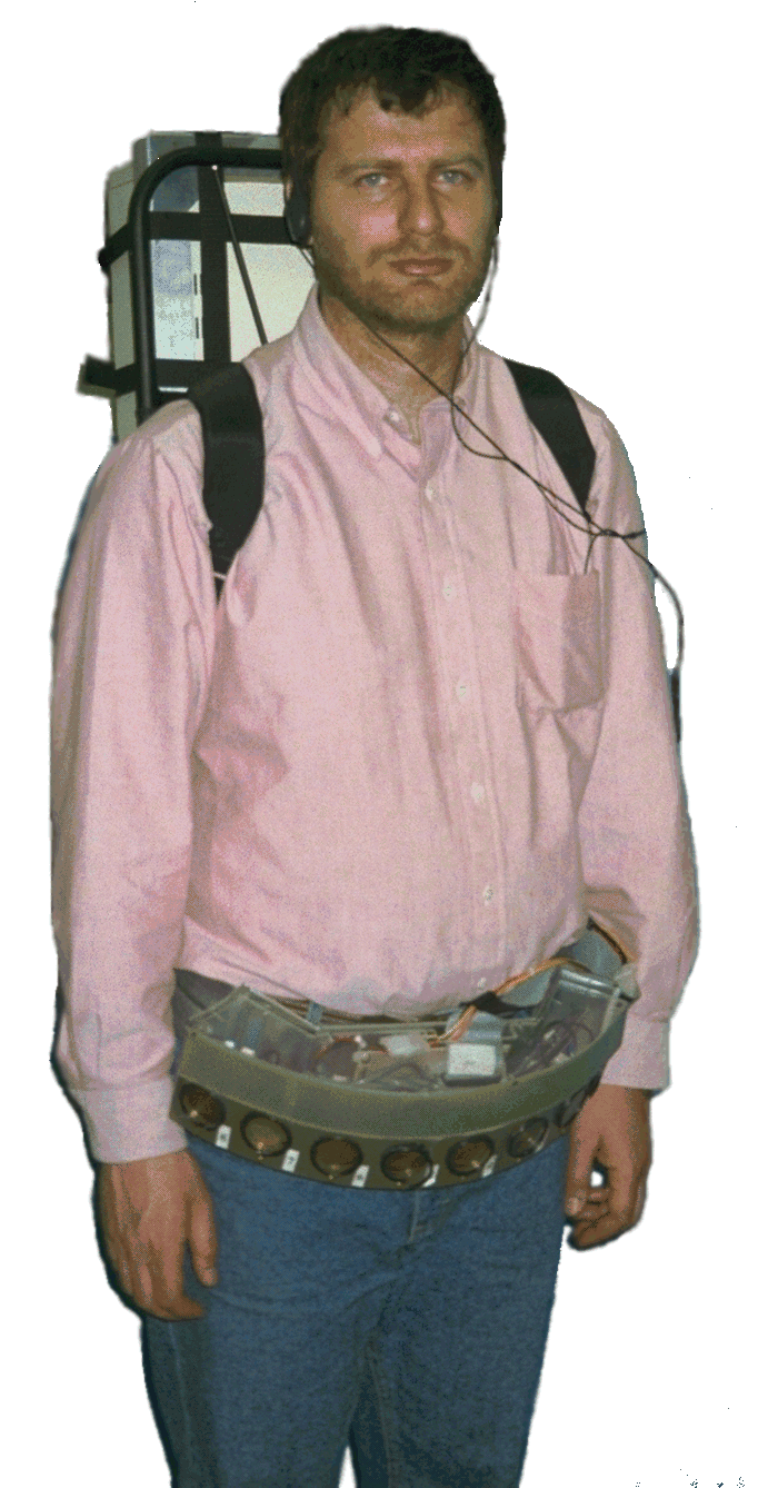
The NavBelt provided two modes of operation:
1. In the image mode the NavBelt produced a 120o-wide view of the obstacles ahead of the user (similar to a radar screen image). This image was then translated into a series of directional (stereophonic) audio cues through which the user could determine which directions were blocked by obstacles and which directions were free for travel. The problem with this method lay in the fact that a considerable conscious effort was required to comprehend the audio cues. Because of the resulting slow response time our test subjects could not travel faster than roughly 0.3 m/sec (1 foot/sec). And even this marginal level of performance required tens of hours of training time.
2. Another mode of operation is called guidance mode. In this mode it was assumed that the system knew the traveler's momentary position and the traveler's desired target location. Under these conditions, the NavBelt needed only generate a single (thus, low-bandwidth) signal that indicated the recommended direction of travel. It was much easier to follow this signal, and walking speeds of 0.6 - 0.9 m/sec (2 - 3 feet/sec) were achieved. The great problem was that in reality the system would not know the user's momentary position, as required by the guidance mode.
II. Detailed Description
In this section we describe in some detail the components of the GuideCane system, and how these components are used to provide the desired functional capabilities.
2.1 System Description
Figure
2: A blind person
walks with the GuideCane.
2.2 Functional Description
Figure
3: 
The
GuideCane sensor-head.
Figure
4: The GuideCane
guides a user around an obstacle.
Figure
5: How the
GuideCane identifies up-steps. An up-step is distinguished from a
vertical wall by the forward-up facing sensor.
Figure
6: Grad. student
Iwan Ulrich demonstrates the GuideCane prototype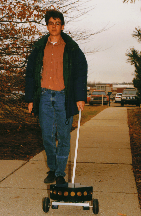
GuideCane identifies the object as stairs. If R2 and R1 are almost equal, then the object is treated as a wall. If R2 is much larger than R1, then the GuideCane interprets the object as an obstacle that needs to be avoided.
2.3 Additional Functions
The utility of the GuideCane can be further enhanced by a variety of other advanced features, although these features are not necessarily unique.
Global Navigation
The GuideCane can be equipped with a Global Positioning System (GPS). Outdoors, commercially available GPSs (which cost less than $1,000) can provide global positioning information to within 20 meters accuracy. This makes it possible for the blind individual to prescribe a desired target location (for example, the supermarket or the post office) to the system and to have the GuideCane automatically guide the user to that location. Alternatively, the system could learn a desired path by recording path segments during an initial "lead-through" run with a sighted person. Indoors, where GPS is not effective, the same path programming or lead-through techniques can be used to have the GuideCane automatically guide the user to a desired location, using dead-reckoning based on encoder and compass readings. This latter method of dead-reckoning is not suitable for long distances because of the unbounded accumulation of odometry errors, but it is suitable for shorter indoor paths.
Wall Following
Many indoor travel tasks take place in long corridors. A technique known as "wall following" can be implemented easily, using only the two sideways facing sonars for navigation.
Speech input/output
A large variety of functions can be implemented with the help of speech output and/or input modules attached to the onboard computer. One useful function could be the instant presentation of exact location and orientation data.
III. Conclusions and Discussion
The GuideCane is unique in that it physically directs the user around obstacles and toward a user-prescribed target. Indeed, the uniqueness is thus twofold:
3.1 Guidance Signals versus Obstacle Information
Existing ETA's are designed to notify the user of obstacles (usually requiring the user to perform some sort of scanning action). Then, the user must evaluate all of the obstacle information, which comprises of the size and proximity of each obstacle and decide on a suitable travel direction. In sighted people (or in animals) such relatively high bandwidth information is processed almost reflexively, usually without the need for conscious decisions. Nature had millions of years to perfect this skill. However, the evaluation of obstacle information presented acoustically is a new skill that must be acquired over hundreds of hours of learning. Even then, exercising such a skill will take a great deal of conscious effort, and thus processing time. The required effort further increases with the number of obstacles found.
The GuideCane is fundamentally different from other devices in that it "views" the environment and computes the momentary optimal direction of travel. The resulting guidance signal is a single piece of information a direction which means that the bandwidth of the information is much smaller. The consequence is that it is far easier, safer, and faster to follow the low-bandwidth guidance signal of the GuideCane than to follow the high-bandwidth information of other existing systems.
3.2 Information Transfer
In our own prior research with the NavBelt (see Section 2.6), we tested different methods of using binaural (stereophonic) signals to guide the user around obstacles. We found that it is generally extremely difficult to recognize and react to such signals at walking speed. Even after nearly 100 hours of training (and many more hours of optimizing the system itself), the Ph.D. student who conducted this research could not walk safely at walking speed. By contrast, when we preliminarily tested the guidance capability of the GuideCane (by having a sighted person steer the guide wheels by remote control), we found that any subject could immediately follow the GuideCane at walking speed and among densely cluttered obstacles.
This success can be credited to another unique feature of the GuideCane: Information transfer through direct physical force. Indeed, there are two different forces that the GuideCane exerts on the user. Both forces are completely intuitive, which means that any user can use the system immediately and without learning how to interpret artificially defined acoustic of tactile signals (as is the case in existing ETAs). Furthermore, yielding to external forces is a reflexive process that does not require a conscious effort. We will briefly describe the nature of these two forces.
3.2.1 Moment due to horizontal rotation of the cane
Even though the GuideCane is basically unpowered (except for the small amount of power needed for steering), the GuideCane can apply a substantial amount of physical force on the user if the user fails to respond to a change of direction prescribed by the device. This force is the result of the sideways motion of the guide wheels when avoiding an obstacle. The resulting rotation of the cane forces a clearly noticeable rotation of the hand that holds the proxal end of the cane.
3.2.2 Change in resistance to pushing the cane
A second force, immediately noticeable after the guide wheels change their orientation (but even before the user feels the rotation of the cane), is the increased reaction force that is opposed to pushing the cane forward. We will not analyze this second force in detail but in essence it can be understood as follows: When walking while the cane and the guide wheels are perfectly aligned, the user must only overcome the reactive force resulting from the friction in the bearings and the roll resistance of the wheels. Let's say this force was equivalent to one pound. Now, suppose the guide wheels steered 60o in either direction. Then the traveler would have to push the cane with a force of 1/cos60o = 2 pounds in order to overcome the 1 pound reactive force of the guide wheels. This change in reactive force is immediately felt by the user and prepares her immediately for an upcoming steering maneuver.
References
1. Benjamin, J. M., Ali, N. A., and Schepis, A. F., 1973, “A Laser Cane for the Blind.” Proceedings of the San Diego Biomedical Symposium, Vol. 12, pp. 53-57.
2. Bissitt, D. and Heyes, A. D., 1980, “An Application of Biofeedback in the Rehabilitation of the Blind.” Applied Ergonomics, Vol. 11, No. 1, pp. 31-33.
3. Blasch, B. B., Long, R. G., and Griffin-Shirley, N., 1989, “National Evaluation of Electronic Travel Aids for Blind and Visually Impaired Individuals: Implications for Design.” RESNA 12th Annual Conference, New Orleans, Louisiana, pp. 133-134.
4. Borenstein, J., Koren, Y., and Levine, S. P., 1991, “Obstacle-Avoiding Navigation System,” U.S. patent #5006988, issued April 9, 1991., 33 claims, (Rights Assigned to the University of Michigan).
5. Borenstein, J. and Koren Y., 1993, “Error Eliminating Rapid Ultrasonic Firing for Mobile Robot Obstacle Avoidance.” U.S. patent #5,239,515 issued August 24, (Rights Assigned to the University of Michigan).
6. Brabyn, J. A., 1982, “New Developments in Mobility and Orientation Aids for the Blind.” IEEE Transactions on Biomedical Engineering, Vol. BME-29, No. 4, pp. 285-289.
7. Clark-Carter, D. D., Heyes, A. D., and Howarth, C. I., 1986, “The Effect of Non-visual Preview Upon the Walking Speed of Visually Impaired People.” Ergonomics, Vol. 29, No. 12, pp. 1575-1581.
8. Freeston, I. L., Callaghan, V. L., and Russell, N. D., 1984, “Portable Navigation Aid for the Blind.” Frontiers of Engineering and Computing in Health Care - 1984 Proceedings, Sixth Annual Conference - IEEE Engineering in Medicine and Biology Society. Los Angeles, California, Sep. 15-17, pp. 247-249.
9. Gilden, D., 1988, “Annual Report of Progress.” Report of the Rehabilitation Engineering Center of the Smith-Kettlewell Eye Research Institute, San Francisco, California, pp. 23-24.
10. Kay, L., 1974, “A Sonar Aid to Enhance Spatial Perception of the Blind: Engineering Design and evaluation.” Radio and Electronic Engineer, Vol. 44, No. 11, pp. 605-627.
11. Kelly, G. W. and Ackerman, T., 1982, “Sona, the Sonic Orientation and Navigational Aid for the Visually Impaired.” 5th Annual Conference on Rehabilitation Engineering, Houston, Texas, p.72.
12. Kumpf, M., 1987, “A New Electronic Mobility Aid For The Blind - a Field evaluation.” International Journal of Rehabilitation Research, 1987; Supplement No. 5 to vol. 10, No. 44, pp. 298-301.
13. Lebedev, V. V. and Sheiman, V. L., 1980, “Assessment of the Possibilities of Building an Echo Locator for the Blind.” Telecommunications and Radio Engineering, Vol. 34-35, No. 3, pp. 97-100.
14. Milner, R. E. and Gilden, D., 1988, “Navigation Device for the Blind.” ICAART 88, Montreal, Canada, pp. 214-215.
15. Shao, S., 1985, “Mobility Aids for the Blind.” Electronic Devices for Rehabilitation, John Wiley & Sons, New York, New York, pp. 79-100.
COMMERCIAL PRODUCTS
Wormald International Sensory Aids, 6140 Horseshoe Bar Rd., Loomis, CA 95650.
2170 ANAIS DO 47º CONGRESSO BRASILEIRO DE CERÂMICA PROCEEDINGS
27 NCAC 01B 0118 PROCEEDINGS BEFORE THE DISCIPLINARY HEARING
4 CONSENT TO PUBLISH FOR CONFERENCE PROCEEDINGS PUBLISHED UNDER
Tags: conference on, annual conference, proceedings, conference, robotics, international
- STATE DIRECTOR’S PRIORITY REQUESTING OFFICE FIELD OFFICE CONTACT
- COLEGIO NACIONAL DE EDUCACIÓN PROFESIONAL TÉCNICA CEDULA DE SEGUIMIENTO
- DESIGNATED STAFF ROLES AND RESPONSIBILITIES SHEET FOR EXTRA PERSONNEL
- ZAD DLA UCZNIÓW KLAS 1 2 NA SPRAWDZIAN Z
- „WZÓR” STATUT UCZNIOWSKIEGO KLUBU SPORTOWEGO „” W ROZDZIAŁ
- KATA PENGANTAR ASSALAMUALAKUM WR WB ALHAMDULLIAH PUJI SYUKUR KITA
- PETITION TO MARCH POLICY 1 A STUDENT WHO
- PROCEDURA ZWIĄZANA Z UZYSKIWANIEM BRAKUJĄCYCH OCEN DO INDEKSU ELEKTRONICZNEGO
- LOS COMITÉS DE ÉTICA ASISTENCIAL SON ÓRGANOS COLEGIADOS DE
- 4º B 20052006 1 PRESENTACIÓN 3 2 CANCIÓN
- MONTHLY BULLETIN APRIL 2013 REPORT DATE 26042013 PAGE
- BÄSTA KLIENT INOM TJÄNSTERNA FÖR PERSONER MED FUNKTIONSNEDSÄTTNING
- 3 TIPOS DE SOCIOS PARA PODER AMPARAR A LAS
- A DMINISTRATIVO JUNTA DE ANDALUCÍA SIMULACRO DE EXAMEN 12
- NATIONAL HISTORY DAY CREATING EXHIBITS ENTRIES SURVIVAL GUIDE GROUP
- ANDISOLS OF THE NILGIRI HIGHLANDS NEW INSIGHT INTO THEIR
- BADMINTON KLUB KUNGOTA TEKMOVALNI PRAVILNIK REKREATIVNE TRUMP LIGE 1
- EMERGENCY MANAGEMENT MUTUAL AID PLAN EMMA FORM 1 RESOURCE
- GOVERNMENT OF PAKISTAN PAKISTAN PUBLIC WORKS DEPARTMENT NO
- 5 LĪGUMA PROJEKTS LĪGUMS NR … PAR NEAPDZĪVOJAMU TELPU
- DIVORCIOINTERNETCOM DESDE 360€ (HONORARIOS DEL LETRADO PROCURADOR E IVA
- OMPIPIBOG06INF1 PROV PAGE 6 E OMPIPIBOG06INF1 ORIGINAL ENGLISH DATE
- UREDNIŠTVO ČASOPISA “POZNAŃSKIE STUDIA SLAWISTYCZNE” OBRAĆA SE S MOLBOM
- DÉLNYÍRSÉGI TÖBBCÉLÚ ÖNKORMÁNYZATI KISTÉRSÉGI TÁRSULÁS 4320 NAGYKÁLLÓ SOMOGYI BÉLA
- 02AMPLOS PODERES SIMPLES A QUEM CONFERE(M) AMPLOS GERAIS E
- DRUŽINSKA PRIJAVNICA RAZLOG BIVALIŠČE (KRAJ ULICA HŠT POŠTA) STANOVANJE
- ALGUNAS PLACAS PRIMERO RAGÙ INGREDIENTES PARA 4 PERSONAS 23
- 36 CULTURE AND SELFWORTH RUNNING HEAD CULTURE AND COMPARISON
- APPLICATION FORM (PLEDGE FORM) FOR WHOLE BODY DONATION NAMEFATHERHUSBANDWIFE
- SIREHO – SISTEMA DE REGISTRO DE CONTRATOS DE PRESTACIÓN
10 PRZYRODA KLASA PIĄTA WYMAGANIA EDUKACYJNE NA POSZCZEGÓLNE
EN EL MUSEO TE LO CUENTO TALLERES INFANTILES EN
 ŠOLSKI CENTER VELENJE VIŠJA STROKOVNA ŠOLA EKONOMIKA PODJETJA ZAPISKI
DEBATES EN TORNO A LOS “PAGARÉS DE CONSUMO” AUTORES
 ODEAT DATA POSTOASYS RELEASE 431 (END OF AUGUST 2009)
RELACIÓN DE CENTROS CONCERTADOS Y AUTORIZADOS EN MATERIA DE
 ICE AGE CRUSTAL SINKING LAB SKILLS AND OBJECTIVES •
 DAVEK NA DODANO VREDNOST KUPONI PODROBNEJŠI OPIS 2 IZDAJA
PROGRAM OF STUDY GENERAL MEDICINE COURSE EPIDEMIOLOGY
ОБРАЗЕЦ В (НАИМЕНОВАНИЕ СТРАХОВОЙ ОРГАНИЗАЦИИ АДРЕС) ОТ
 TITLE MOBILE SERVICE PROVIDERS MOVE TO AN ENDTOEND LTE
KIMBALL THEATRE PRODUCTION PROPOSAL FOR WILLIAM & MARY
 HOSPITAL MUNICIPAL CLÍNICOQUIRÚRGICO DR JULIO M ARISTEGUI VILLAMIL CÁRDENAS
4 RITO PROCESSUAL OPÇÃO OU SUJEIÇÃO? POR OROCIL JUNIOR
 NÄMND FÖRVALTNING DATUM 20 6 UTVÄRDERING AV NYFIKET EN
 POWIATOWE CENTRUM POMOCY RODZINIE W STARGARDZIE TEL (091) 48
SEMINARIOTALLER MIGRACIÓN INTRAFRONTERIZA EN AMÉRICA CENTRAL PERSPECTIVAS REGIONALES SAN
TABLE S1 SUMMARY OF THE RESULTS OF THE LABORATORY
 7 SUMMARY SHEETS E MIXTURES A MIXTURE CONTAINS TWO
 DETERMINADOR INDIVIDUAL DE LA HUMEDAD DE LOS GRANOS KETT
