CERNST2000053 FEBRUARY 2000 DESIGN AND CALCULATION OF AN EARTH
CERNST2000053 FEBRUARY 2000 DESIGN AND CALCULATION OF AN EARTH
DESIGN AND CALCULATION OF EARTH ELECTRODE
CERN-ST-2000-053
February, 2000
DESIGN AND CALCULATION OF AN EARTH ELECTRODE
J. Gomez
Abstract
People using electrical installations have to be protected against electrical shock. For purposes of protection a distinction is made between direct and indirect contact. Direct contact is contact with a live conductor. Protection is provided by the insulation of cables or the screening of live parts. An indirect contact happens when someone touches exposed metal parts which are not intended to carry current but have become live as a result of a fault. In this case metallic parts raise the metal to a dangerous potential (contact voltage). Here protection is provided by connecting the exposed metal part (i.e. the case of the electrical machine) to the earthing point of the installation. A protective device will disconnect the circuit as soon as a fault current flows to earth. The earth fault value will depend on the impedance of the path taken by the fault current, which is known as the earth fault loop. The resistance of the earth electrode plays an important role in the final impedance of the earth fault loop, especially when the neutral of the transformer is earthed without any impedance. A good earth electrode should have the lowest possible value compared with the rest of the earth loop (voltage divisor). If this can be achieved, the contact voltage will be limited and the current that trips the protections will be of a higher value. The maximum duration of a contact voltage is established according to IEC 60364-4 413.1.1.1. An important constraint in obtaining a good resistance value for the earth electrode is the resistivity of the soil.
SOIL RESISTIVITY
The resistivity of a given type of soil will vary by several orders of magnitude as a result of small changes in the moisture content, salt concentration, and soil temperature. A broad variation of resistivity occurs as a function of soil types. Knowledge of exactly what type of soil we have at a given site will help to design in a precise manner the earth electrode.
Table 1: Resistivity values of the earthing medium
|
Medium |
Resistivity (Ωm) |
||
|
|
Minimun |
Average |
Maximun |
|
City, industrial area |
|
1000 |
10 000 |
|
Surface soil, loam |
1 |
|
50 |
|
Clay |
2 |
|
100 |
|
Sand and gravel |
50 |
|
100 |
|
Surface limestone |
100 |
|
10 000 |
|
Limestone |
5 |
|
4000 |
|
Shale |
5 |
|
100 |
|
Sandstone |
20 |
|
2000 |
|
Granite, basalt |
|
10 000 |
|
|
Decomposed gneiss |
50 |
|
500 |
|
Freshwater lake |
|
200 |
200 000 |
|
Sea water |
20 |
100 |
200 |
|
Pastoral, low hills, rich soil |
|
30 |
|
|
Marsh |
2 |
100 |
|
|
Pastoral, medium hills |
|
200 |
|
|
Fill, ash, cinder |
6 |
25 |
70 |
|
Rocky soil, steep hills |
10 |
500 |
1000 |
|
Clay, shale, gumbo |
3 |
40 |
200 |
|
Gravel, sandstone, with little clay or loam, granite |
500 |
1000 |
10 000 |
|
Sandy, dry, typical coastal country |
300 |
500 |
5000 |
PRINCIPAL TYPES OF EARTH ELECTRODE (ADVANTAGES AND DISADVANTAGES)
|
Type |
Advantages |
Disadvantages |
|
Ring ground |
Easy to design and to install (especially around an existing facility). Readily available. Can be extended to reach water table. |
Not useful where large rock formations are near surface. |
|
Horizontal bare wires (radials) |
Can achieve low resistance where rock formations prevent use of vertical rods. |
Subject to resistance fluctuations with soil drying. |
|
Horizontal grid (bare wire) |
Minimum surface potential gradient. Easy to install if done before construction. Can achieve low resistance contact in areas where rock formations prevent the use of vertical rods. Can be combined with vertical rods to stabilize resistance fluctuations. |
Subject to resistance fluctuations with soil drying if vertical rods not used. |
|
Vertical rods |
Simple design. Easiest to install particularly around an existing facility. Hardware readily available. Can be extended to reach water table. |
Not useful where large rock formations are near surface. Step voltage on earth surface can be excessive under high fault currents.
|
|
Plates |
Can achieve low resistance contact in limited area. |
Most difficult to install. |
|
Incidental electrodes (pipes, foundations, buried tanks) |
Can show very low resistance. |
Little or no control over future alterations. Must be employed with other electrodes. |
CALCULATION OF EARTH RESISTANCE
For this purpose a straightforward design based on graphs is proposed.
General points:
Choose the configuration of the earth electrode according to the shape of the facility.
Calculate the resistance to earth for the configuration.
Check if the calculated resistance meets the design goal.
Complete the design to include all necessary interconnections.
Steps to calculate the earth electrode:
Starting data: configuration, resistivity, length and diameter of rods.
Determine the resistance of one of the ground rods from Fig. 1. Start by drawing a line between the chosen diameter ‘d’ and the length ‘l’. Then indicate the crossing point in ‘q’. From this point place a line between ‘q’ and the resistivity and read the resistance at the point where the line crosses ‘R’.
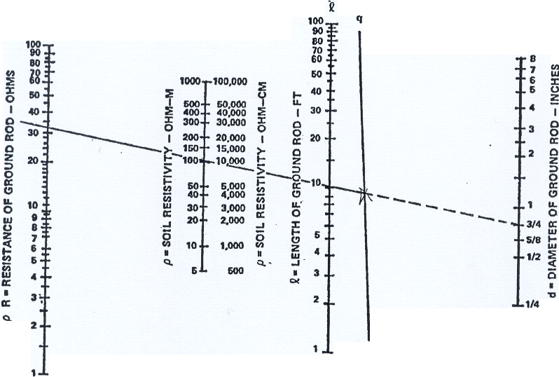
Figure 1: Nomograph for determining the resistance to earth of a single ground rod.
Because we are going to place more than one rod there will be a lower resistance which will be estimated according to Fig. 3.
If the rods are distributed in a grid pattern, as will frequently be done for substations, use Fig. 2 to estimate the net resistance instead of Fig. 3.
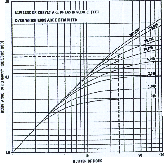
Figure 2: Graph of multiple rod resistance ratio.
Conversion values:
1 foot = 30.4 cm 1 inch = 2.54 cm
Example:
To illustrate this, let us assume that a 30 m 48 m (100 ft 160 ft) rectangular configuration like that shown in Fig. 3 is initially chosen. Assume that the soil resistivity measurements made during the site survey showed an average resistivity of 10 000 ohm-cm for the area. In addition, the site survey indicated that all rock formations are at depths greater than 10 feet; the water table (layer containing a big amount of flowing water) never drops more than 5 feet below grade; and the frost line extends only to 1 foot below ground level.
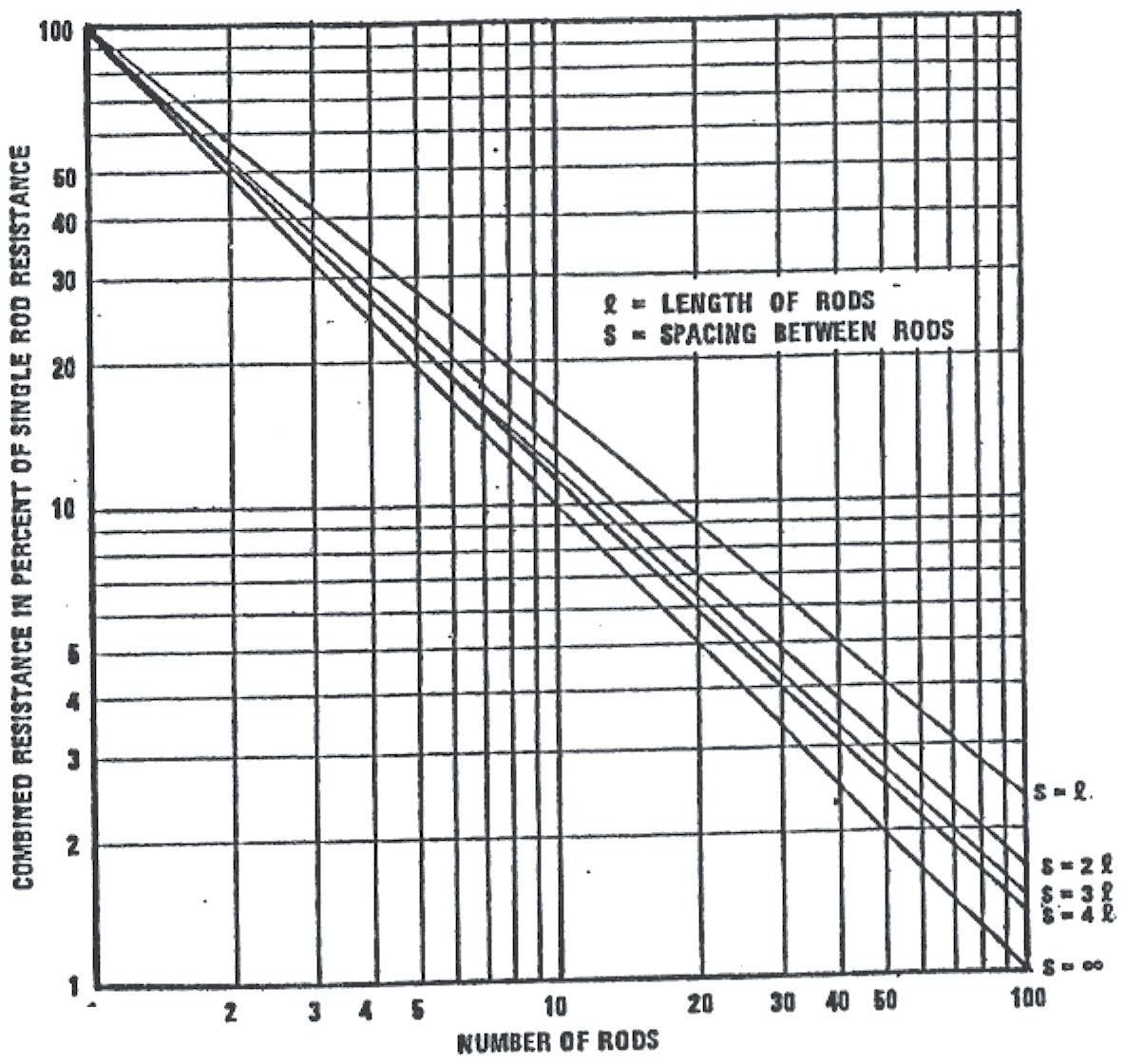
Figure 3: Effective resistance of ground rods when arranged in a straight line or a large circle.
Therefore, 3 m (10 ft) ground rods are initially selected for evaluation. (Minimum rod diameter 14.8 mm or 3/4 inch.)
First in Fig. 2 we place a straight edge between the point marked 3/4 on line ‘d’ and the point marked 10 ft on line ‘l’. Indicate on line ‘q’ where the straight edge crosses. Next, place the straight edge between the point just marked on ‘q’ and the 10 000 ohm-cm point on the vertical line marked as resistivity. Then read the resistance as 32 ohm-cm at the point where the straight edge crosses the vertical line tagged resistance.
In order to prevent interactions between rods (placing rods too close increases the expected resistance) we assume an initial spacing of 7 m (20 m) or twice the rod length. Figure 1 shows that 26 rods are needed to encircle the building. Then we use Fig. 3 to determine the relative lowering of resistance of one rod that is produced by 26 rods in parallel. The answer is 5.5%.
The resistance of the 26 rods in a 10 000 ohm-cm soil is:
R = 32 x 0.055 = 1.76 ohms.
Figure 3 applies to ground rods placed in a straight line or around the perimeter of a site whose dimensions are large with respect to the rod spacing. If the rods are distributed in a grid use Fig. 2.
For this example, we have an area of 16 000 square feet (1450 m2) and 26 rods distributed in it, so the graph shows a multiplier of 0.056.
R = 32 x 0.056 = 1.9 ohms.
This calculation method does not consider the interconnecting cable between rods because the effect produced by the rod on the earth resistance is more important than the one produced by 7 m of bare cable. If the distance between rods is bigger then 7 m should be considered.
Wire resistance should be considered in parallel with the rods.
For this purpose we can use two formulas:
Buried straight rod or wire
h = depth of burial (cm)
L = total length (cm)
r = ohm-cm
R = 0.366 r/L (log (L/d) + log (L/4h) + 0.34) h < 0.4L
Buried circle of wire
R = 0.366 r/L (log (L/d) + log (L/4h) + 0.81) h > 0L
Vertical rod
R = 0.366 r/L (log (3L/d)
When a vertical rod is driven through a high-resistivity superficial layer into a lower resistivity subsoil, an adjustment can be made to the resistance to earth expression by substituting a reduced ‘effective length’ of the ground rod. L will be the effective length.
L= L – h (1 – (r2/r1)) where L is the length of the rod, r1 is the resistivity of the upper layer, r2 is the resistivity of the subsoil, and h is the depth of the upper layer.
DESIGN GUIDELINES
Where bedrock (meaning an underground layer formed by rocks) or other obstacles prevent the effective use of vertical rods, horizontal wires, grids, or radials should be used.
When other alternatives are not possible or are not cost-effective, chemical enhancement (salting) is frequently the only choice left.
The nominal spacing between rods should be between one and two times the length of the rod; however, it is necessary for a ground rod to be placed near each lightning down conductor, so spacings should be limited to not more than 15.2 m.
The rods and interconnecting cable comprising the earth electrode subsystem should be positioned between 0.6 m and 1.8 m outside the dripline of the building or structure to insure that rain, snow, and other precipitation wets the earth around the rods.
Where two or more structures or facilities are located in the same general area (less than 60 m away) and are electrically interconnected with signal, control, and monitor circuits, either provide a common earth electrode subsystem or interconnect the separate earth electrode subsystems with two buried bare cables.
To minimize voltage differentials between the two structures, the facilities should effectively share a common earth electrode subsystem. Separate structures spaced closer than 6 m should have a common earth electrode subsystem installed that encircles both facilities.
Structures or facilities having no interconnecting cables and separated by a distance greater than 60 m generally do not require their earth electrode subsystems to be interconnected.
Metallic structures near the earth electrode subsystem should be connected to reduce the danger of potential differences during lightning or fault protection; their connection will also reduce the resistance to earth of the electrode subsystem.
To minimize resistance variations caused by surface drying of the soil and by the freezing of the soil during winter, connections, interconnecting cables, and tops of ground rods should be buried at least 0.3 m below grade level and the interconnecting cable at least 0.45 m below grade level.
Access to the earth electrode subsystem should be provided through the installation of one or more grounding wells at each site. Removable access covers must be provided.
More than one grounding well may be necessary depending upon the size of the facility, the extent of the electrode subsystem, and the degree of accessibility to the electrodes.
Locate at least one of the ground wells in an area with access to open soil so that resistance checks of the earth electrode subsystem can be made once the building is in use.
Bibliography
[1] Grounding, bonding, and shielding for electronic equipments and facilities – US Department of Defense handbook.
[2] Grounding principle and practices II – Establishing grounds, Jensen Claude.
[3] Guide de protections des reseaux industriels, Christophe Preve.
[4] Puesta a tierra de equipos eléctricos, Francisco Ruiz Vasallo.
Tags: calculation of, this calculation, design, february, earth, calculation, cernst2000053
- CHIEF EXECUTIVE OFFICER UNITUS CAPITAL PAGE 7 POSITION SPECIFICATION
- CONDENSADORES DE HID DE TENTA ELECTRIC DE TAIWÁN
- NAME DATE IT’S CATCHING KEY WORDS INFECTIOUS PROCEDURE
- ESPECIALIDAD EXCURSIONISMO REQUISITOS Y RESPUESTAS 1 DISCUTE CON
- SLOVENSKÁ POŠTA A S POSTSERVIS SEKCIA LOGISTIKY BOJNICKÁ 14
- LIBERAL EDUCATION SPRING 2001 VOLUME 87 NUMBER 2
- ANSWERS TO FINAL EXAMS – SHORT COURSES LOCATED AT
- CONSEJERÍA DE EDUCACIÓN Y FORMACIÓN PROFESIONAL DIRECCIÓN GENERAL DE
- IMPUESTO SOBRE VEHÍCULOS DE TRACCIÓN MECÁNICA (CONSULTA VINCULANTE V094913
- LESSON 1 VECTORS AND COORDINATE SYSTEMS I POSITION VECTOR
- BIL 4837 TYP GENERAL BILL GB INB HOUSE IND
- YEMASSEE INDIAN NOTES LOCATED IN THE LOW COUNTRYTHE
- PREGUNTAS Y RESPUESTAS DE UNA ENTREVISTA DE TRABAJO 1
- LA CARTA DEBE IR CON PAPEL MEMBRETEADO DE LA
- PROBLEMAS RESUELTOS CAMPO ELECTRICO 8 CAMPO ELECTRICO I
- NEC TECHNOPHILE BUSINESS & EDUCATION SECTORS WITH ITS LCD
- BOARD OF UTAH STATE PARKS AND RECREATION MEETING DEPARTMENT
- BOARD OF REGENTS’ MEETING ACTIVITIES SCHEDULE JUNE 2122 2005
- DEPARTMENT FOR ENVIRONMENT FOOD AND RURAL AFFAIRS BIODIVERSITY
- LEDARINFORMATION KRISPLAN FÖR LEDARE I EN FÖRENING KAN EN
- CURRICULUM VITAE UNIVERSIDAD DEL CAUCA ADJUNTE UNA FOTOGRAFÍA RECIENTE
- SØKNAD TIL FYLKESMANNEN OM TILSKUDD 2013 FOREBYGGING AV UØNSKEDE
- KEMENTERIAN PENDIDIKAN DAN KEBUDAYAAN INSTITUT TEKNOLOGI SUMATERA JALAN TERUSAN
- POWIATOWY ZESPÓŁ SZKÓŁ NR 3 W KOŚCIERZYNIE KOŚCIERZYNA DNIA
- TEMPLATE FOR USE BY BC SOCCER MEMBERS AND AFFILIATED
- TETFUNDESSD10LRPROFILERES BATCH NO OF SUBMISSION………… … TETFUND INSTITUTIONBASED RESEARCH
- TC ALANYA ALAADDİN KEYKUBAT ÜNİVERSİTESİ LİSANSÜSTÜ EĞİTİM ENSTİTÜSÜ TEZSİZ
- T ISKOVÁ ZPRÁVA MANPOWERGROUP INDEX TRHU PRÁCE Q2 2020
- (VARDAS PAVARDĖ) (FAKULTETAS PAREIGOS) KLAIPĖDOS UNIVERSITETO REKTORIUI
- GGI DOWNSCALED SPATIALLY EXPLICIT SOCIOECONOMIC SCENARIO DATA 2007 TECHNICAL
ORDEN DE 17 DE JULIO DE 2002 POR LA
EJERCICIOS DE FÍSICA 3º ESO CON RESULTADOS 1
Kodeks Tenisa Prema Usta (američka Teniska Asocijacija) 1 Prije
 POOLED LIST CODE FOR A GP PRACTICE AUTHORISED SIGNATORY
RAZPISNA DOKUMENTACIJA JAVNI RAZPIS ZA SOFINANCIRANJE INOVATIVNIH TURISTIČNIH
NAZWA MIEJSCOWOŚCI DATA SĄD REJONOWY W ……………… …WYDZIAŁ RODZINNY
PRESENTACIÓN PIKOR TEATRO 2008 TEATRO BARAKALDO (“PISA LA RAYAZAPALDU
 POWERPLUSWATERMARKOBJECT1405033 CLUB MILITAR AFILIACIÓN DE SOCIOS Y AUTORIZACIÓN DE
 GOODWILL AMBASSADOR HANDBOOK STAFF CONTACTS JOHN BECKORD – PRESIDENT
ELA – GRADE 6 UNIT 2 ELL
FIŞA DISCIPLINEI ANUL UNIVERSITAR 20202021 1 DATE DESPRE PROGRAM
DNEVNA PRIPRAVA ZA DODATNO STROKOVNO POMOČ OŠ SAVA KLADNIKA
ACTA DE LA JUNTA EXTRAORDINARIA COMUNIDAD DE PROPIETARIOS EUROPAGOLF
UMOWA O ZAKAZIE KONKURENCJI PO USTANIU STOSUNKU PRACY
STUDY CLOSURE FACEPAGES 3122022 PAGE 2 OF 2 UCSD
PUNTOS DE CONTACTO DE CEIS EN ANDALUCÍA NOMBRE CEI
 GRUPOS SOLIDARIOS DE MICROCRÉDITO Y REDES SOCIALES SUS IMPLICANCIAS
 ¡ BIENVENIDOS AL MARAVILLOSO MUNDO DE LA TRIGONOMETRIA! MONTOYA
 STUDENTIŠKOS MUZIKOS IR POEZIJOS KONKURSO „SPROGMUO“ DALYVIO ANKETA VARDAS
JUEVES 14 DE NOVIEMBRE DE 2013 DIARIO OFICIAL (PRIMERA
