SAFETANK® DOUBLE WALL TANKS HIGH DENSITY CROSSLINKED POLYETHYLENE STORAGE
SAFETANK® DOUBLE WALL TANKS HIGH DENSITY CROSSLINKED POLYETHYLENE STORAGE
- ~~
SAFE-Tank® Double Wall Tanks
HIGH DENSITY CROSSLINKED POLYETHYLENE Storage Tanks
PART 1-GENERAL
1.01 Requirements
The CONTRACTOR shall provide a SAFE-Tank® double wall, high density crosslinked polyethylene tanks and accessories per section 2.05, complete and in place, in accordance with the Contract Documents.
Unit Responsibility: The CONTRACTOR shall be responsible for furnishing the SAFE-Tank® double wall tank(s) and its accessories as indicated.
1.02 REFERENCES, CODES AND STANDARDS
A. American Society of Testing Materials (ASTM).
1. D638 Tensile Properties of Plastics
2. D883 Standard Definitions of Terms Relating to Plastics
4. D1505 Density of Plastics by the Density-Gradient Technique
5. D1525 Test Method for Vicat Softening Temperature of Plastics
6. D1693 ESCR Specification Thickness 0.125" F50-10% Igepal
7. F412 Standard Terminology Relating to Plastic Piping Systems
B. ANSI Standards: B-16.5, Pipe Flanges and Flanged Fittings
C. Building Code: Uniform Building Code, [1997 J Edition] / IBC 2000
D. ARM: Low Temperature Impact Resistance (Falling Dart Test Procedure).
1.03 SUBMITTALS
A. Shop Drawings: Shop drawings shall be approved by the engineer or contractor prior to the manufacturing of the SAFE-Tank® double wall tank(s). Submit the following as a single complete initial submittal. Sufficient data shall be included to show that the product conforms to Specification requirements. Provide the following additional information:
SAFE-Tank® double wall tank and Fitting Material
Resin Manufacturer Data Sheet
b. Fitting Material
c. Gasket style and material
Bolt material
Dimensioned Tank Drawings
Location and orientation of openings, fittings, accessories, restraints and supports.
Details of manways, flexible connections, and vents.
Calculations shall be stamped and signed by a registered, third party engineer where required.
Wall thickness. Hoop stress shall be calculated using 600 psi @ 100 degrees F.
Tank restraint system. Show seismic and wind criteria.
Electrical heat tracing installation details if required. (Required or delete section)
Insulation data if required. (Required or delete section)
B. Manufacturer’s warranty
C. Manufacturer's unloading procedure (see Poly Processing Company Installation Manual)
Manufacturer's installation instructions (see Poly Processing Company Installation Manual)
Supporting information of Quality Management System.
Manufacturer’s Qualifications: Submit to engineer a list of 5 installations in the same service as proof of manufacturer's qualifications.
H. Factory Test Report
Material, specific gravity rating at 600 psi @ 100 degrees F. design hoop stress.
2. Wall thickness verification.
3. Fitting placement verification.
4. Visual inspection
5. Impact test
Gel test
Hydrostatic test
1.04 QUALITY ASSURANCE
A. The SAFE-Tank® double wall tanks of the same material furnished under this Section shall be supplied by Poly Processing Company or approved equal who has been regularly engaged in the design and manufacture of chemical storage tanks for over 10 years.
B. Tanks shall be manufactured from virgin materials.
1.05 WARRANTY
A. The warranty shall be provided upon request for the specific service application. For most chemical applications, Poly Processing Company offers a limited 5 year full replacement warranty. See Poly Processing Company’s chemical specific positions and warranty statement.
PART 2 – PRODUCTS
2.01 General
A. Tanks shall be rotationally-molded, high density crosslinked polyethylene, double wall, flat bottom tanks. The assembly consists of one cylindrical, closed top inner primary tank and one cylindrical, open top containment outer tank. Each tank is a rotationally molded one-piece seamless constructed tank. The SAFE-Tank® tanks are designed for above-ground, vertical installation and are designed to store approved chemicals at atmospheric pressures. The assembly shall be designed to prevent rainwater and debris from entering the containment tank. Tanks shall be adequately vented as prescribed in Poly Processing Company’s Technical Bulletin, Venting-Design for ACFM (air cubic feet per minute). Where indicated, tanks shall be provided with ancillary mechanical fittings and accessories. Tanks shall be marked to identify the manufacturer, date of manufacture and serial numbers must be permanently embossed into the tank.
2.02 MANUFACTURER
A. Tanks shall be manufactured by Poly Processing Company
2.03 POLYETHYLENE STORAGE TANKS
A. Service: Chemical storage tanks shall be suited for the following operating conditions:
B. High Density Crosslinked Polyethylene resin used in the tank manufacture shall be by Exxon Mobil Chemicals or equal and shall contain ultraviolet stabilizer as recommended by resin manufacturer. Where black tanks are indicated, the resin shall have a carbon black compounded into it. The tank material shall be rotationally molded and meet or exceed the following properties:
|
Property |
Type I XLPE |
ASTM Test |
|
Environmental Stress Cracking Resistance, F50, hours, 10% Igepal |
>1,000 |
D1693 |
|
Tensile Strength, Ultimate psi, 2-inch/minimum |
2,830 |
D638 Type IV Specimen |
|
Elongation at Break, % ,2-inch minimum |
700 |
D638 Type IV Specimen |
|
Flexural Modulus, psi |
86,780 |
D790 |
C. Wall thickness for a given hoop stress is to be calculated in accordance with ASTM D 1998. Tanks shall be designed using a hoop stress no greater than 600 psi. In NO case shall the tank thickness be less than design requirements per ASTM D 1998.
1. The wall thickness of any cylindrical portion at any fluid level shall be determined
by the following equation:
T = P x OD/2SD or 0.433 x SG x H x OD/2SD
Where: T = wall thickness, in
P = pressure, psi
SG = specific gravity, gm/cc
H = fluid head, ft
OD = outside diameter, ft
SD = hydrostatic design stress, 600 psi
The minimum wall thickness shall be sufficient to support its own weight in an upright position without external support but shall not be less than 0.187” thick.
2. On closed top tanks the top head shall be integrally molded with the cylindrical wall. Its minimum thickness shall be equal to the thickness of the top of the straight sidewall. In most cases, flat areas shall be provided for attachment of large fittings on the dome of the tank.
3. The bottom head shall be integrally molded with the cylindrical wall. Knuckle radius shall be:
-
Tank Diameter, ft
Min Knuckle Radius, in
less than or equal to 6
1
greater than 6
1-1/2
4. Tanks with 3000 gal capacity or larger shall have at least 3 lifting lugs. Lugs shall be designed for lifting the tank when empty.
a. Unless otherwise indicated, manways shall be 19-in diameter or greater and equipped with an emergency pressure relief device or SAFE-Surge™ Manway.
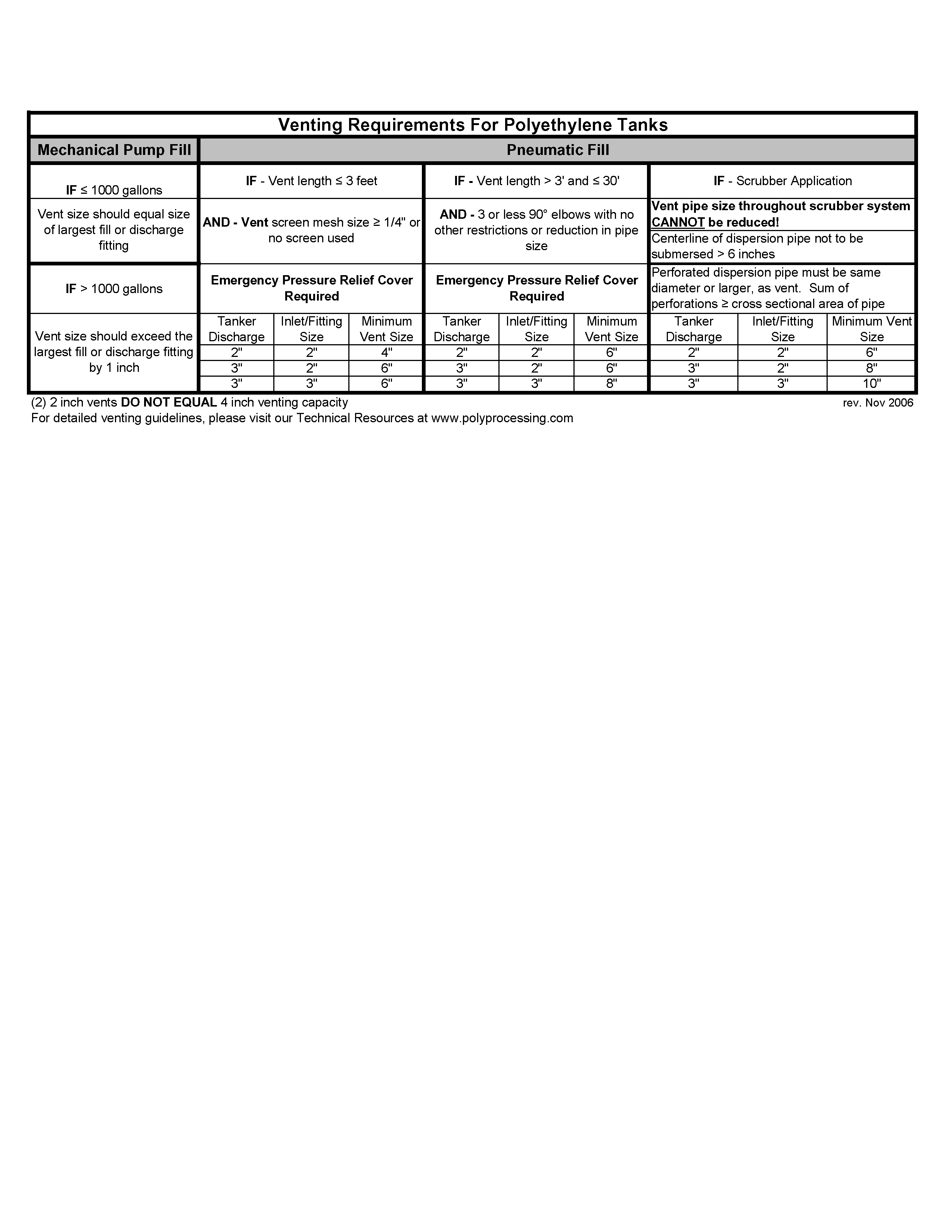
b. Unless otherwise indicated, bolted sealed top manway shall be 19- inches or greater and be in locations easily accessible from the nearest worker access position. The sealed manway shall be constructed of polyethylene material. The bolts shall be chemically compatible with the chemical being stored. Gaskets shall be closed cell, crosslinked polyethylene foam, Viton, or EPDM materials. NOTE: If pneumatically filling, venting must be in accordance with the following:
D. Tank colors shall be natural (unpigmented), black (compounded), or other (compound colors) as specified by the ENGINEER with written agreement by the tank manufacturer.
2.04 TANK ACCESSORIES
A. Ladder: (Choose one or delete section)
1. [Painted carbon steel], {fiberglass}, [galvanized carbon steel] or [stainless steel] access ladders shall be provided with the polyethylene chemical storage tanks at locations as shown. Use proper chemical resistant materials when anchoring to tank dome or sidewall. Safety cages shall be added to ladders as required. Ladders must be designed to OSHA standard 2206; 1910.27.
2. Ladders must be secured to the tank and secured to the concrete to allow for tank expansion / contraction due to temperature and loading changes. See Poly Processing Company’s Tank Installation Manual.
3. All ladders shall be designed to meet applicable OSHA standards. Reference:
OSHA 2206; 1910.27; fixed ladders.
B. Restraint System: (Choose one or delete section)
Metal components to be galvanized, stainless steel, or painted clips, edge softeners, and tension ring with stainless steel or galvanized cables and clamps.
(Choose or delete section)
Seismic system to be designed to meet the proper seismic zone and specified wind load. PE stamped calculations and or drawings may be required based on individual project requirements.
2.05 TANKS:
Tank Schedule per the following specifications
Note 1: Approximate overall height is measured along the straight cylindrical portion of the tank and includes the dome top.
Fittings
Tank fittings shall be according to the fitting schedule below. Fitting, gasket and bolt material shall be per requirements in section A, or a material that is compatible with the product being stored and shall be a minimum of ¼-in thick. Threaded fittings shall use American Standard Pipe Threads. If tanks are insulated, fittings shall be installed at the factory prior to application of the insulation. All bottom discharge connection must maintain and meet the requirements to support 110% secondary containment requirements.
Double flange fittings shall be constructed of virgin polyethylene. Bolts will be welded to a common backing ring and encapsulated with polyethylene preventing fluid contact with the metal material. Flange will have one full face gasket to provide a sealing surface against the flange and tank surface. Bolt holes shall straddle the principal centerline of the tank
Bolted flange bulkhead fittings shall be constructed with one 150-lb flange installed inside the tank and one flange ring installed outside the tank. The flange will be socket or threaded according to specific connection requirements. The head of the bolts shall be encapsulated with polyethylene preventing fluid contact with the metal material. Encapsulated heads shall have a gasket to provide a sealing surface against the flange. Bolt holes shall straddle the principal centerline of the tank.
Down Pipes and Fill Pipes: Down pipes and fill pipes shall be supported at 6-ft max intervals. Down pipes and fill pipes shall be PVC or material compatible with the chemical stored.
U-Vents: Each tank must be vented for the material and flow and withdrawal rates expected. Vents should comply with OSHA 1910.106(F)(iii)(2)(IV)(9). U-vents shall be sized by the tank manufacturer and be furnished complete with insect screen if required (Insect screen lessens the tank capacity by 1/3) in accordance with the venting schedule listed above.
Flange Adapters: Adapters may be used to adapt threaded or socket fitting components to 150-lb flange connections. Adapters shall be of material compatible with the chemical stored.
2.06 LEVEL INDICATION (Choose one or delete section)
A . Float Indication: The level indicator shall be assembled to the tank and shall consist of PVC float, indicator, polypropylene rope, perforated interior pipe, PVC roller guides, clear PVC sight tube and necessary pipe supports. The level indicator shall act inversely to the tank contents and shall not allow entrance of tank contents into the sight tube at any time.
B. Ultrasonic Level Indicator: The ultrasonic level indicator shall be, (to be specified), and suitable for service in a non-hazardous/hazardous environment.
2.07 TANK INSULATION AND HEAT TRACING (Choose or delete section)
A. To be installed by Poly Processing Company
2.08 FACTORY TESTING
A. Material Testing
1. Perform gel and low temperature impact tests in accordance with ASTM D 1998 on condition samples cut from each polyethylene chemical storage tank.
Degree of Crosslinking. Use Method C of ASTM D 1998- Section11.4 to determine the ortho-xylene insoluble fraction of crosslinked polyethylene gel test. Samples shall test at no less than 60 percent.
Tank Testing
1. Dimensions: Take exterior dimensions with the tank empty, in the vertical position. Outside diameter tolerance, including out-of-roundness, shall be per ASTM D 1998. Fitting placement tolerance shall be +/- 1/2-in vertical and +/- 1 degree radial.
Visual: Inspect for foreign inclusions, air bubbles, pimples, crazing, cracking, and delamination.
3. Hydrostatic test: Following fabrication, the bottom tanks, including inlet and outlet fittings, shall be hydraulically tested with water by filling to the top sidewall for a minimum of 1/2 an hour and inspected for leaks. Following successful testing, the tank shall be emptied and cleaned prior to shipment.
PART 3 - EXECUTION
3.01 DELIVERY, STORAGE, AND HANDLING
A. The tank shall be shipped upright or lying down on their sides with blocks and slings to keep them from moving. AVOID sharp objects on trailers.
B. All fittings shall be installed and, if necessary, removed for shipping and shipped separately unless otherwise noted by the contractor.
C. Upon arrival at the destination, inspect the tank(s) and accessories for damage in transit. If damage has occurred, Poly Processing Company shall be notified immediately.
3.02 INSTALLATION
A. Install the tanks in strict accordance with Poly Processing Company’s Tank Installation Manual and shop drawings.
3.03 FIELD TESTING
A. Poly Processing Company recommends that all tanks be hydro-tested for 24 hours prior to commissioning.
End Of Section
Tags: crosslinked polyethylene, of crosslinked, safetank®, storage, crosslinked, tanks, double, density, polyethylene
- 1 ÜCRETLI ÖĞRETMENLERIN BAŞVURU İŞLEMLERI ÜCRETLI ÖĞRETMEN OLMAK
- KURS „HISTORISCHE GRUNDBEGRIFFE“ SCHLOTHEUBER VIII KAISER KÖNIG KÖNIGSWÄHLER 7
- MINISTARSTVO POLJOPRIVREDE NA TEMELJU ČLANKA 33 STAVKA 2
- OTTAVA DI NATALE – MESSA DI FINE ANNO MARIA
- REPUBLIKA HRVATSKA KARLOVAČKA ŽUPANIJA OPĆINA VOJNIĆ KLASA4000101190115 URBROJ21331701411901 VOJNIĆ
- PRESSEMITTEILUNG NR 1409 VIERZIG METER HOCHSCHULE ESSLINGEN DIE HOCHSCHULE
- CARIBBEAN UNIVERSITY DECANATO ACADÉMICO ESCUELA GRADUADA RECINTO DE [BAYAMÓNCAROLINAVEGA
- H OOGHLY RIVER BRIDGE COMMISSIONERS (A STATUTORY ORGANISATION UNDER
- CONSTITUCIONALISMO GLOBALIZACIÓN Y DERECHO MANUEL ATIENZA UNIVERSIDAD DE ALICANTE
- 20212022 DIETETIC INTERNSHIP CALENDAR WEEK DATES ACTIVITY ROTATION DAYS
- X JORNADAS DE DIÁLOGO FILOSÓFICO PENSAR Y CONOCER A
- MERGERS AMALGAMATIONS & ACQUISITIONS IN THE AUSTRALIAN NOTFORPROFIT HUMAN
- AMERICAN LIBRARY ASSOCIATION COMMITTEE INFORMATION UPDATE PLEASE NOTE ALA
- CURRICULUM COMMITTEE TERMS OF REFERENCE THE GOVERNING BODY AT
- 1863 – 1864 M SUKILĖLIŲ ĮATMINTINIMO ARCHITEKTŪRINĖS IDĖJOS AIŠKINAMASIS
- CENTRAL PENNSYLVANIA CONFERENCE UNITED METHODIST MEMOIRS 19702010 (FOR EARLIER
- ACCESSIBLE APPS FOR IOS DEVICES BY JOLENE NEMETH
- INFO OM UTBILDNINGAR PÅ SLU I ALNARP PÅ SLU
- KOMORA DAŇOVÝCH PORADCŮ ČR POBOX 121 657
- A PPENDIX D HAZARD ANALYSIS PROCESS INSTRUCTOR GUIDE APPENDIX
- APPLE VOLUME PURCHASING PROGRAM (VPP) POLICY WORKING DOCUMENT (SUMMER
- LOK SABHA CORRIGENDA TO THE TRIBUNALS REFORMS BILL
- 1 CORE DETAILS A PPLICATION FOR AUTHORISATION APPLICATION FORM
- OŚWIADCZENIE JA NIŻEJ PODPISANYA 1 OŚWIADCZAM ŻE WYRAŻAM ZGODĘ
- MODULO DISEÑOS EXPERIMENTALES Y ANALISIS DE DATOS CURSO DE
- 121ª FERIA DE IMPORTACION & EXPORTACION DE CHINA 15
- ARKIV H10 ARKIVSAKSNR 200867142 SAKSBEHANDLER STEIN KULØ DATO 08032010
- ESSAY STRUCTURE CONTENTS ESSAY STRUCTURE 1 ESSAYS
- SUBPOENA GUIDE TO CHILD PROTECTION DOCUMENTS TYPES OF
- LAS MEZCLAS DAR A CONOCER LA GASTRONOMÍA DE SUIZA
149 STRAIPSNIS IŠŽAGINIMAS 1 TAS KAS LYTIŠKAI SANTYKIAVO SU
 LES TYPES DE MARCHÉS I LE MARCHÉ A UN
 4(4) FRÅGOR OCH SVAR OM OMBUDSFUNKTIONEN I 1177 VÅRDGUIDENS
 SCENARIUSZ SPOTKANIA PAŹDZIERNIK 2015 5 UCZTA PODANO DO
LEA TR DIRECTOR TELEPHONE FAX EMAIL ADDRESS ADDRESS
LEY 816 DE 2003 (JULIO 07) DIARIO OFICIAL NO
TALDEKA EGITEKO JARDUERAK GOGOETAK DEIALDIA EGOKITZAPEN SOZIOLINGUISTIKOA EGOKITZAPEN TESTUALA
 MUSTAFA KEMAL UNIVERSITY FOREIGN RELATIONS OFFICE ADDRESS MUSTAFA KEMAL
 1 STL FICHE TECHNIQUE R EALISATION D’UN FROTTIS 1
 EXEC DOCS MASTER LIST JULY 2000 – MARCH 13
 INSTITUTO MUNICIPAL DE ECOLOGÍA FORMATO PARA LA SOLICITUD DE
 PROJECT QUALITY MANAGEMENT PROCESS PROJECT QUALITY MANAGEMENT PROCESS© FOR
BSV PROTOKOLLVERTEILERLISTE SEITE 2 VON 2 VERTEILERSCHLÜSSEL UND ADRESSENLISTE
PRODUCAO LOGÍSTICA E MATERIAIS I CÓDIGO CAD1009 NOME PRODUCAO
 PRACTICUM (ASIGNATURA 1734) GRADO DE CYTA NOMBRE DEL ALUMNO
HUISWERKOPDRACHT DE OPDRACHT IS EEN ANALYSE MAKEN VAN HET
SECCIÓN I ANIMALES VIVOS Y PRODUCTOS DEL REINO ANIMAL
 NÚMEROS Y OPERACIONES 1 COLOCA EL SÍMBOLO “MAYOR QUE”
 KOMME I GANG MED MICROSOFT EASY ASSIST PUBLISERT MAI
CANADA AND MULTINATIONALISM POLITICAL SCIENCE 101 PROFESSOR CRAIGE TA
