RELIABILITY OF MEMS CASE STUDY BEGON MARTIN JANVIER
1 CALIBRATION AND RELIABILITY TESTS OF ENVIRONMENTAL MOBILE SENSORS18 M ODULE PEPASU115 RELIABILITY OF NONREPAIRABLE COMPONENTS M
18 THE RELIABILITY AND VALIDITY OF LAST MENSTRUAL PERIOD
329 RELIABILITY AND ITS RELATION RELIABILITY AND
6TH INTERNATIONAL SYMPOSIUM ON RELIABILITY ENGINEERING AND RISK MANAGEMENT
ALAY S & KOÇAK S (2002) VALIDITY AND RELIABILITY
Realiability of Digital Micromirror Device (DMD)
Reliability of MEMS : case study
|
Begon Martin Janvier 2007 Ciapala Richard Deaki Zoltan
Reliability of MEMS : Case Study |
|

Reliability of the
Digital Micromirror Device

|
Section |
Microtechnique, Master 1er semestre
|
|
Professeur |
Herbert Shea |
Table des matières
1 Introduction 3
1.1 What’s a DMD 3
1.2 How does it work? 3
1.2.1 The components 3
1.2.2 The motion 4
1.3 The applications 4
1.4 Chronology of the development of the DMD 5
2 Tests on reliability 6
2.1 Failure modes and solutions 6
2.1.1 Hinge memory 6
2.1.2 Hinge Fatigue 9
2.1.3 Stiction 10
2.1.4 Environmental robustness 11
2.2 Final characteristics 11
3 Conclusion 13
4 References 14
1Introduction
The purpose of this paper is to study how the work has been done to assure a good enough reliability for a specific MEMS, in our case, the Digital Micromirror Device developed by Texas Instruments during the last 20 years. We will especially focus on the way problems relative to the hinge have been dealt with and how it improved the reliability of the device. We will also discuss briefly other critical topics such as the stiction of the mirror on the landing site and the environmental robustness of the DMD.
1.1What’s a DMD
The DMD chip is a micromirrors matrix. Each micromirror is 16 μm square and there’s a gap of 1 μm between them, making it a 17 μm pitch. It reacts with a processor that allows each mirror to move in two directions that could refer to on or off. With this matrix and the fact that micromirrors reflect light, the system is able, when illuminated, to reflect the light and project an image on a screen, depending on the input signal generated by the electronic and the synchronization with the colour wheel.
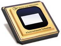
Figure 1: DMD chip [8]
1.2How does it work?
Let’s now have a look at how the system works:
1.2.1The components
The chip is composed of 4 stages. The first one contains the CMOS SRAM memory that will, after removing or applying the bias voltage, move the mirror.
The second stage is composed of the metal address pads as well of the landing sites.
The third one contains the torsion hinge that will allow the rotation of the mirror because of its small size and the address electrodes that will effectively make the mirror move.
The final stage is the mirror itself and allows the reflection to be effective.
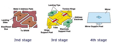
Figure 2: Stages composing a DMD chip [11]
1.2.2T he
motion
he
motion
As you can see on figure 3, the mirrors can rotate around a unique axis defined by the torsion hinges from 10° to –10° whether the electrode on the right side or the one on the left side is engaged.
Each electrode has its controller so that each mirror can be controlled independently.
1.3The applications
The main purpose of this device is to be used in a Digital Light Processing (DLP) system as the main component.
A DLP system consists in 5 basics elements:
DMD chip
Light source
Colour filter system
DLP electronics
Optical projection lens
Figure 3: Digital Light Processing (DLP) system [8]
The light source emits light that goes through the colour filter. The DMD chip then, controlled by all the electronics, moves the mirrors in order to create an image which is magnified by an optical system and projected on a screen. In order to get the right image, the movement of the DMD has to be synchronized with the rotation of the colour wheel. Pixels appear lighter or darker depending on the frequency which is used to tilt the corresponding mirrors back and forth.
Other emerging applications for the DMD are 3D metrology, confocal microscopy, holographic data storage and digital TV [7].
1.4Chronology of the development of the DMD
1981 - First 128 x 128 digital micromirror device (DMD) developed
1984 - First DMD (digital micromirror device)-based printer produced
1988 - First digital DMD produced
1992 - First large-screen color DMD projector demonstrated
1993 - First high-resolution DMD projection demonstrated
1995 - Dr. Hornbeck, DMD™ inventor, receives Eduard Rhein Award
1997 - TI inventors Hornbeck, Nelson receive Rank Prize Funds award for DMD™
2Tests on reliability
After this brief introduction and explanation of the Digital Micromirror Device, we will now discuss the reliability of the device.
As you can see in the chronology, this device has been developed for quite a while now and Texas Instrument has been performing ongoing tests for a long time showing that the DMD is exceptionally robust and reliable.
In fact, a great number of tests have been performed on this device with the FMEA (Failure Mode and Effect Analysis) method and a group of experts from various disciplines came together to identify possible failure modes. We are now going to highlight the different failure modes and the way their effects on reliability have been considered.
2.1Failure modes and solutions
Reliability mandates that we perform tests at stresses beyond product specifications. It can apply to various stress types such as temperature, voltage, mechanical (number of mirror landings, mirror duty cycle), chemical, or light. For the DMD, all of these stresses were tested in an attempt to identify potential weaknesses. As the tests identified weaknesses, a team evaluated the results to determine if the test stress was well beyond the needed stress or if design/process changes were necessary. [2]
We are now going to describe the potential failure mechanisms of the DMD and the solutions and tests developed to eliminate them. There are four main domains identified as affecting the reliability of the DMD [1,2,3]:
Hinge memory
Hinge fatigue
Stiction
Environmental robustness (includes shock and vibration failure)
2.1.1Hinge memory
O ne
of the most significant modes of failure is the hinge memory, it is
in fact the only known life limiting failure exhibited by the DMD
[2]. It occurs when a mirror operates in the same direction for a
long period of time, for example when the mirror is continually
turned off-side as the corresponding pixel has to appear dark in the
projected image.
ne
of the most significant modes of failure is the hinge memory, it is
in fact the only known life limiting failure exhibited by the DMD
[2]. It occurs when a mirror operates in the same direction for a
long period of time, for example when the mirror is continually
turned off-side as the corresponding pixel has to appear dark in the
projected image.
H
Figure
4 : The micromirrors in the back have a
residual tilt angle compared to the ones in the front, it is due to
the hinge fatigue [4]
The main factors that contribute to hinge memory failure are the duty cycle and the operating temperature. The duty cycle is the percentage of time a mirror is addressed to one side (on or off), for instance a 95/5 duty cycle means that 95% of the time the mirror is addressed to one side and the other 5% of the time, the mirror is addressed to the other side. The duty cycle used for the tests is 95/5 but isn’t representative of home or cinema entertainment where the duty cycle is more likely to be 15/85 or 25/75 at maximum. REFERENCES ???

Figure 5: Duty cylce effects on hinge memory [5]
To accelerate hinge memory a life test was created under standard condition of 65°C and 5/95 duty cycle and it appeared that the more time the system operates the more the bias voltage had to increase to annihilate the residual tilt angle. The graph below shows the characteristic between the bias voltages and the number of non functional mirror through the time. [3]
Figure 6 : Evolution of the bias voltage through the time, reported to the number of non functional micromirros [3]
We can observe the curve shifting to the right as the length of the test increases, indicating the need for higher bias voltage to operate the mirror properly. By repeating these tests on many devices (several hundreds) and comparing the results, it has been stated that the hinge memory phenomenon is predictable and a shortened life test has been elaborated. A series of tests have then been conducted at different operating temperatures and duty cycles and the results showed that temperature is the dominant factor for hinge memory lifetime. [3]
Hinge memory is caused by metal creep of the hinge material. So in order to minimize it alternate materials and processes have been evaluated. This led to the selection of a new material that had a much lower degree of metal creep to replace aluminium. This first improvement increased lifetime by a factor of 5 but was not sufficient to guarantee a good enough reliability (only 1000 hours in worst-case).
The second step towards reliability was the implementation of stepped VDD and a “bipolar reset” which allowed the mirrors to be efficiently controlled over a wider range of hinge memory. This also increased lifetime by a factor of 5 to about 5000 hours in worst-case situation.
The thermal management of the DMD device was then addressed as it seems evident it affects the lifetime of the device. Several sources of heat contribute to hinge memory. The primary source is radiant energy from the light source because it heats up the entire package significantly. Heatsinks are in fact attached to the back of most packages in order to keep the temperature in the device as low as possible. The second significant source of heat is the rest of the equipment composing the DLP projector and surrounding the DMD. An efficient thermal management design is required. In most application developed to date, the DMD operates at temperatures only 7 to 10 °C above the projector ambient. An efficient heat management added to the previously cited improvements can ensure a lifetime greater than 40000 hours. [3]

Figure 7: Hinge memory mean lifetime estimates over testing time [4]
2.1.2Hinge Fatigue
The fatigue is the slow growth of a crack driven by repeated plastic deformation leading to failure. The start of the crack lies where the concentration of stress is the highest, and so is often localized at holes, sharp corners, scratches or corrosion.
The fatigue is one of the most significant concerns for the DMD for the obvious reason that the mirror in normal operating mode switches every 200 microseconds and that each time the hinges are used in torsion.
Simple calculations in operating use shows that for a 5 years use at 1000 operating hours per year, the mirrors have to switch 90x109 times to ensure reliability. [3]
The first finite element analysis using bulk properties of aluminium (initial hinge material) shows that fatigue should be a great concern, however after leading some experimentation, using an acceleration factor, it has been stated that either on tests sample or production sample, the number of cycles generally exceeds 100 x 109 and on several samples more than 1012 cycles without any sign of fatigue.
This is due to the thin film properties of the metal and therefore the finite element analysis should consider these properties instead of bulk properties to establish the model.
The macroscopic model for fatigue is based on dislocation piling up at the surface of the metal and by the way creating stress concentration at sharp corners, scratches and so on. For extremely small structures such as the hinges in the DMD (some grain thick) the accumulation of density of dislocations is not big enough to form fatigue crack.
The fatigue inspection of a used hinge with a transmission electron microscope showed no evidence of dislocation, grain irregularity, or fatigue, even at the section of the hinge where the most stress was expected.
2.1.3Stiction
Stiction failures of the device are induced by an excessive adhesive force between the landing tip and its landing site [10]. This problem occurs when the stiction force is sufficiently high to keep the mirror from moving when the electronic reset sequence is applied.
Adhesive forces can be induced by surface contamination, capillary condensation, CMOS defects and van der Walls forces.
Surface contamination can be observed as a result of improper surface cleaning during the superstructure processing [3].
A reliability testing can be done to measure the distribution of surface adhesion across the device to determine the number of operating devices under different switching voltages. Figure 10 shows that as the magnitude of the voltage is decreased certain mirrors will cease to function due to adhesion forces. In this particularly figure two devices were taken after 160hours of life test, curve A is the distribution of mirrors from a sample of production and curve B is the distribution of mirrors from a proposed process change. It is clear that curve B was not as robust as curve A.
In the early stages of the DMD development it was observed that adhesion forces were too great to deliver a reliable device, therefore a solution was found to overcome this problem by implementing springs on the landing tips of the mirror. When the mirror lands on the surface the spring will bend and store energy that will help the mirror to take off the surface when the reset pulse is applied and the bias voltage removed, the spring can be observed on Figure 9.
To avoid capillary condensation the device is sealed in a controlled atmosphere and then sealed in a robust hermetic package.
Van der Walls forces are minimized by the deposition of a special thin self-limiting anti-stick layer, this layer will help to lower the surface energy of the contacting parts.
All these methods will help to ensure the reliable reset operation of the DMD.
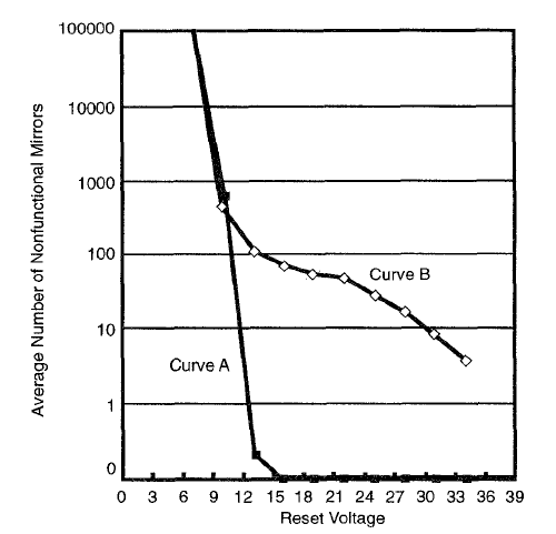
Figure 8: Number of nonfunctional mirrors versus reset voltage [?]
2.1.4Environmental robustness
As mentioned in the stiction part for the capillarity forces, one great concern in reliability for all the MEMS is the problem of robustness to the environment in which it has to work properly.
The environmental tests on the DMD are based on the standard test requirement for the semiconductors [2]. The table below shows typical environment tests used for design specification and validation.
Table 1 : DMD environmental tests [2]
As one could think and because of its small size, the DMD may appear fragile, but in contrary its small size is what actually enables its robustness. The DMD is impervious to mechanical shocks and vibrations at low frequencies since its lowest resonant frequency is in the kilohertz. Furthermore, TI has tested the DMD chip through 1500G and 20G vibration with no failure due to mirror breaking.
Finally one critical element for the DMD chip is its package. Its robustness has been one of the main concerns throughout the development of the chip and its reliability. The hermeticity of the package is one of the most important factors in the high-reliability of the device. The glass window and its optical properties are also critical in order to obtain the high quality image inherent to the DMD.
2.2Final characteristics
3Conclusion
The reliability of the DMD has been one of the main concerns throughout the development of this device. A lot of time has been put into its improvement and many changes have been made in order to assure a big lifetime for this product. Each problem has been considered in depth and solutions were found to make its impact on overall reliability minimal. We can also notice that some apparently important concerns like hinge fatigue turned out to have no significant effect whereas other problems that could have been considered as secondary at the first sight have big implications on the reliability.
We can say that the Digital Micromirror Device is today very reliable due to all the work and improvements that have been done to it. The reliability management of this device is exemplary and should be considered as a reference for the development of other MEMS devices.
4References
L.A. Yoder, “An introduction to the digital light processing (DLP) technology”, DLP Technology (22.02.2005)
M.R. Douglass, “DMD reliability: a MEMS success story”, SPIE Proceedings Vol. 4980 (2003)
M.R. Douglass, “Lifetime Estimates and Unique Failure Mechanisms of the Digital Micromirror Device (DMD)”, 36th Annual International Reliability Physics Symposium, Reno, Nevada (1998)
A.B. Sontheimer, “Digital Micromirror Device (DMD) Hinge Memory Lifetime Reliability Modeling”, 40th Annual International Reliability Physics Symposium, Dallas, Texas (2002)
A.B. Sontheimer, “Effects of Operating Conditions on DMD Hinge Memory Lifetime”, 41st Annual International Reliability Physics Symposium, Dallas, Texas (2003)
S.J. Jacobs et al., “Hermicity and Stiction in MEMS Packaging”, 40th Annual International Reliability Physics Symposium, Dallas, Texas (2002)
http://www.dlp.com/dlp_technology/default.asp
http://en.wikipedia.org/wiki/Digital_Micromirror_Device
Larry J. Hornbeck, “Digital Light Processing™: A New MEMS-Based Display Technology.”
ARTICLE 7 POWER RELIABILITY R840 REPORT OF IMPENDING EMERGENCIES
CHAPTER 5 EXERCISE VALIDITY AND RELIABILITY EXERCISE PROVIDE A
CHAPTER SUMMARY CHAPTER 4 VALIDITY RELIABILITY AND GENERALIZABILITY
Tags: begon martin, janvier, martin, reliability, begon, study
- ROLE PLAYS CHARACTER PROMPTS AND PASSPORTS YOU ARE A
- WWWPROLOCOSSTIT INFOPROLOCOSSTIT “TRA CASTELLI E LEGGENDE” DAL 21 AL
- 20 CONVENIO DE PARÍS PARA LA PROTECCIÓN DE LA
- PROCESO ADQUISICIÓN DE BIENES Y SERVICIOS FORMATO ESTUDIOS Y
- ‘HOW DO YOU THINK I FEEL? IT’S MY COUNTRY’
- LA CUBIERTA ESPACIO EN EVOLUCIÓN EL OBJETIVO DE LA
- 1 ÍNDICE DE INSTRUMENTOS DEL PATRIMONIO INMOBILIARIO FEDERAL NOTARÍA
- ANNEXE 4 NOTICE D’ACCOMPAGNEMENT DU TABLEAU DES OBJECTIFS
- ALTILLOCOM INSTITUCIONES DEL DERECHO DERECHO CONJUNTO DE NORMASLEYES
- OPEN SOURCE MECHANISMS THE EXAMPLE OF BIOS1 ▬▬▬▬▬▬▬▬▬▬▬▬▬▬▬▬
- SURAT KUASA UNTUK MENGHADIRI RAPAT UMUM PEMEGANG SAHAM TAHUNAN
- COLLOQUE DU RÉSEAU INTÉGRATION NORD SUD (RINOS) MONTRÉAL 13
- OVERVIEW CHARLOTTEMECKLENBURG STREAM AND LAKE BUFFER REQUIREMENTS
- NATIONAL DISABILITY AUTHORITY PRELIMINARY DISCUSSION PAPER ON COMMISSIONING WE
- PREDLOG NA PODLAGI 7 ČLENA ZAKONA O ŠPORTU (URADNI
- ZÁVĚREČNÁ ZPRÁVA O REALIZACI PROJEKTU PROGRAMU TRANS V ROCE
- TOSHIBA SATELLITE 1200 HOW TO TAKE APART LAPTOP STEP
- LEY 3335 SANCIONADA 291199 PROMULGADA 141299 DECRETO NUMERO
- UNA DEFINICIÓN MENOS TÉCNICA DEL ASPERGER EL SÍNDROME DE
- SECTION 10 4400 FIRE PROTECTION SPECIALTIES LANL MASTER
- KODE ETIK KEMAHASISWAAN UNIVERSITAS IQRA BURU UNIVERSITAS IQRA BURU
- GİZLİ TC ……KAYMAKAMLIĞI İLÇE MİLLİ EĞİTİM MÜDÜRLÜĞÜ SABOTAJLARA KARŞI
- EL BALONMANO REGLAMENTACIÓN EN UN PRINCIPIO EL BALONMANO SE
- AZ AMERIKAI FORRADALOM ESZMETÖRTÉNETI HÁTTERE ÉS ANNAK MEGÍTÉLÉSE A
- 1 TÉTEL A GYÓGYPEDAGÓGIA FOGALMA ÉRTELMEZÉSE (TÁRGYA CÉLJA FELADATAI)
- NAME DATE ANATOMY OF A WAVE WORKSHEET
- PROFESSIONAL GROWTH INCREMENT SUMMARY OF ACTIVITIES NAME DEPARTMENT
- CONSENTIMIENTO INFORMADO PARA LA UTILIZACIÓN DE MUESTRAS BIOLÓGICAS
- MARINE AND ESTUARY RESOURCES FOR STUDENTS ESTUARIESGOV LINKS TO
- ZAŁĄCZNIK NR 4 DO UCHWAŁY SENATU UNIWERSYTETU MEDYCZNEGO WE
DEPARTMENT OF EDUCATION ADVANCES TRANSPARENCY AGENDA FOR ACCREDITATION ACCREDITATION’S
 PODER LEGISLATIVO PROVINCIA DE TIERRA DEL FUEGO ANTÁRTIDA E
South Carolina General Assembly 117th Session 20072008 a27 r49
ECETRANSWP1520079 PAGE 3 INF7 WORKING PARTY ON THE TRANSPORT
ELLSWORTH FARMERS EXCHANGE PO BOX 98 6509 CENTER STREET
 NORTHWEST FISHERIES SCIENCE CENTER NATIONAL MARINE FISHERIES SERVICE 2007
 BUPATI BENGKULU UTARA PROVINSI BENGKULU PERATURAN BUPATI BENGKULU UTARA
SPOLEK RODIČŮ PŘI MATEŘSKÉ ŠKOLE PŘÍBRAM VIII ŠKOLNÍ 131
 10 OPTIMIZACION CAPITULO 5 ALGORITMOS DE APROXIMACIÓN A
Click Here to Proceed
 HISTORIAL COMPRENSIVO (COMPREHENSIVE HISTORY) PÁGINA 5 DE 5 APELLIDO
 G ENERALITAT DE CATALUNYA DEPARTAMENT DE CULTURA OFICINA DE
PROCES VERBAL AL ȘEDINȚEI CONSILIULUI DE OBSERVATORI AL INSTITUȚIEI
DDª CON DNI NÚMERO SECRETARIOA DE LA AMPA
 72 SESION ORDINARIA NO0082018 DEL 19 DE ABRIL 2018
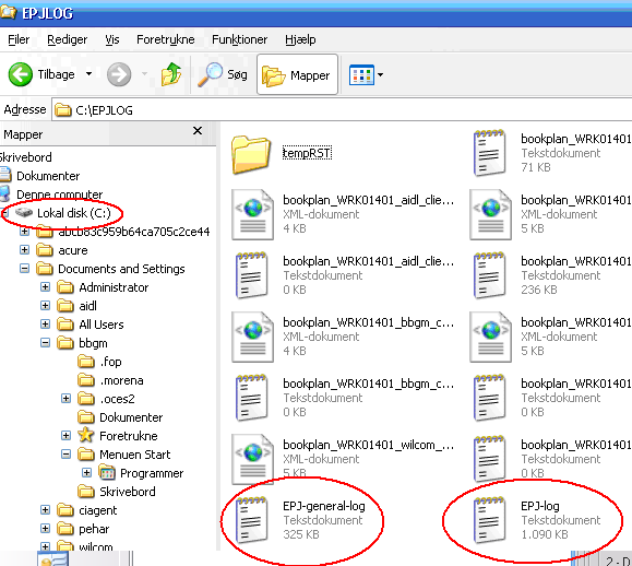 SÅDAN FINDER MAN EPJ LOGFILER HØKLIK PÅ START –
 A NEXO 8 MÓDULO DE FORMACIÓN EN CENTROS DE
NR 17845227032018 ANEXA NR 1 OPERATOR ECONOMIC (DENUMIREANUMELE)
NAMING IONIC COMPOUNDS WORKSHEET NAME THE FOLLOWING IONIC COMPOUNDS
 NAME DURING THE 17TH AND 18TH CENTURIES (THE
