TWIG PROTECTOR TWIG PROTECTOR EASY TWIG ASSET LOCATOR TWIG
HP OPENVIEW STORAGE DATA PROTECTOR 55 SUPPORTED DEVICES19 EFECTO FOTOPROTECTOR SISTÉMICO DEL ALFA TOCOFEROL ÁCIDO ASCÓRBICO
ASOCIACIONES Y PROTECTORAS DE ANIMALES EN ASTURIAS ANADEL (ASOCIACIÓN
“DIRK THE PROTECTOR” GARY PAULSEN STORY MAP 1 WHAT
BELLOWS PROTECTOR PROCEDURE T PAGE T NICOL 060106 ENSURE
CHAPTER 9 POWER SHARING IN LEBANON FOREIGN PROTECTORS DOMESTIC
TWIG PROTECTOR
TWIG Protector
TWIG Protector Easy
TWIG Asset Locator
TWIG Dog Locator
Configuration Guide
Publication number: YZ3301-12
All rights reserved. © Twig Com Ltd, 2011-2013.
Due to differences in use, user interface, number of buttons and hardware, all settings may not be applicable to each device version. Please consult your service provider or Twig Com Support for full details.
For any further questions please contact Twig Com support at [email protected] or +358 40 510 5058.
Table of Contents:
1. Installing software and drivers 3
2. Opening connection 3
3. Device information 4
4. General configuration settings 4
PIN Code 4
ID 5
Service Center Number 5
Automatic answer 5
MPTP header translation 5
Use Google Format with postion messages 5
Contrast value 5
Power Saving Mode 5
5. GPS & status messaging settings 6
GPS Sleep time 6
Max GPS search time 6
Status messages 7
Generic application sound level 7
Lost GSM beep tone interval. 7
6. GPRS settings 7
ID 7
APN 8
GPRS server port number 8
GPRS IP address/domain 8
GPRS DNS 1-2 8
GPRS user name 8
GPRS password 8
Backup SMS number 8
GPRS Connection mode 8
Reconnect interval 8
GPRS usage 9
GPRS international roaming blocking 9
7. Assistance call 9
Assistance numbers 9
8. White list 9
9. Man down alert 10
Alerts when 10
No alarm duration: 11
Pre-Alarm duration: 11
Motion sensitivity: 11
Man Down Angle 11
Normal status delay 11
Man Down sensor on/off] 11
Man Down sensor usage mode 11
10. Twig SOS settings 11
Phone Number and Name 12
11. Twig SOS Settings 2 12
MPTP SOS Text 12
MPTP MD Text: 12
MPTP RF SOS Text: 12
Wireless alert unit serial number 13
Vibrator enabled 13
Display enabled: 13
Message resending, 13
Power off disabled 13
Emg call continue 13
Power up self test 13
Poweroff when docekd 13
Emergency number text 13
Post Emergency beep 14
SOS Activation mode 14
Event Start delay 14
Full SOS Cycles 14
Call timeout 14
Activation method timeout 14
Cancellation period 14
END Key Timeout 14
SOS tones sound level 14
Speaker level 14
EMG ACK timeout 14
12. Amber Alert a.k.a. Condition Check 14
Mode 14
Phone number type 15
Activation number 15
Deactivation number 15
PreAlarm time 15
SOS Text 15
13. Indoor Module 15
14. Internal MPTP command 16
15. Updating software 16
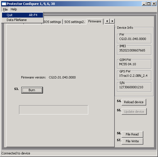
16. Saving data file 16
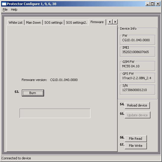
17. Firmware versions 17
You can download the latest TWIG device software (“firmware”) and necessary PC drivers at www.twigcom.com > Support > Downloads.
TGP81EU Run first the USB_driver_install.exe before connecting the unit for the first time.
TCP90EU uses Windows HID, so driver is not needed.
Connect TWIG device to your computer with Mini USB cable. The operating system will notify you of finding new device, and typically install drivers automatically.
If the driver installation fails you may also install drivers manually using Windows find new hardware wizard. Load the device driver files (.dll) from TWIG Support Downloads and store them to your computer.
Installation process may be different depending on your operating system. Installation also requires administrator privileges.
Currently supported operating systems are Windows 2000/XP/Vista/Windows7
Note that since TWIG devices use two ports, the system may prompt for driver installation twice. If this happens, repeat the manual installation of drivers. After the installation is done, you may need to restart and reconnect the device before changes take effect.
To install TWIG Configurator software, download the compressed software file (e.g. Configure_CG1P.01.040.000.exe for TGP81EU models and Configure_CT1P.exe to TCP90EU models) from the Support pages and save it in your computer. The configuration software is ready to be used without separate installation. Make sure the needed device driver (dll)-files are located in same directory as the main program. TWIG Configurator program can includes embedded in it the corresponding device firmware release for TGP81EU, for TCP90EU models there is separate program for FW update. For example, the TWIG Protector firmware release CG1P.01.040.000 is embedded to Configure_CG1P.01.040.000.exe The firmware file to be loaded to device must be of same type as the one already stored in the device. For example, device type CG1P will only allow it to be programmed with firmware type CG1P. Same rule is for the las 4 digits of FW version.
Once the TWIG Configurator software and drivers are installed, you can establish a connection between TWIG device and your computer.
Note that device must be turned on and connected to computer when using the Configurator program.
Connect TWIG device to your computer with Mini USB cable (YC3004) attached to the charging adapter (AUG81) or programming station (AGP81).
Note that the TWIG Desktop charger CTA81 does not support USB connection.
Next open the Configurator software by double-clicking Configure_xxxx.exe-file on your computer.
TWIG device connects automatically to the right COM port and connection with PC is indicated with “Connected to device” text in the user interface lower left corner.
After connecting, the existing device setting values soon appear in their respective fields.
The Device Info box displays details on your TWIG device, including the serial number, IMEI (International Mobile Equipment Identity) code as well as the firmware versions of device and installed modules.
You can access various settings groups by clicking on the tabs on top row.
Note that TWIG device settings are case sensitive. If there are wrong characters or other invalid values entered in a data field, those are ignored and default value is used instead.
Update device –button saves the current settings in the PC program to device.
Reload device -button reads all the settings currently in the device to PC program. This overwrites all data field values in PC program.
File read will read configure_save.bin file from the Configure.exe working directory and its settings values will appear in the PC program.
File Write will write the current settings values in the PC program to configure_save.bin –file in the working directory.
More information on how to use different file names later in section Saving data file.
Depending on the version of the device hardware, installed firmware version or the configurations made, all settings may not be available or in use may cause conflict and malfunction.
Note that if the device has already been configured remotely from central station (for example TWIG WebFinder SP), care should be taken not to interfere with the remote settings when using TWIG Configurator.
Reboot device -button will restart the unit and reload settings from device to Configurator program. Reboot is needed after uploading settings to device by Update device –button.
Factory reset –button will clear all settings from the unit and store factory defaults.

PIN Code
PIN code (4 digits) is used to unlock Protector’s SIM card, unless you are using a SIM card in which the PIN code request is disabled. Default value for PIN code is 9999. Replace the value with your own PIN code, or leave unchanged if PIN request is disabled in the SIM card. If the PIN code is defined incorrectly, you won’t be able to turn on your Protector. After three failed attempts, the SIM card will be blocked. If your SIM card gets blocked, you need a PUK code (8 digits) to open it. Remove the SIM card from the TWIG device and install it into a phone compatible with your SIM card. When trying to open the phone, it will prompt you for the PUK code. After entering the PUK code, key in a new PIN code. You can then install the SIM card back to your TWIG device. If you fail to key in the correct PUK code 10 times in a row, your SIM card will be permanently blocked. If this happens, contact your network operator to get a new SIM card.
ID
You can define identification for your TWIG device. This code may contain both numbers and letters, and it is case sensitive. Default value for the ID code is: Protector. Currently this value is not sent in MPTP messages
Service Center Number
Defines the SMS number where generic Mobile Originated MPTP messages such as low battery or docking & undocking notifications are sent. The same number is also authorised to transmit remote configuration via SMS.
Automatic answer
Allows restricting incoming calls and automatic answer for incoming calls. As default all incoming calls are allowed and they are shown to user as incoming call.
Note that if white list is in use the handling of calls or calls and SMS’s will override this setting.
MPTP header translation
Translate header defines whether special characters (? and !) in the beginning of SMS based MPTP messages are replaced by letters or not. Replacement is necessary in some mobile phone networks where operator uses these for their own purposes.
Translate header: OFF ON
Requests: ? Q
Updates: ! E
Default value is OFF.
Note that the Translate header setting needs to be configured identically in the central station, whether it is a monitoring server system or a TWIG Discovery.
Use Google Format with postion messages
Enables mode where all outgoing messages are sent as hyperlink. Data fields from the end of message are in brackets in the end of hyperlink
Contrast value
Contrast value slide changes device screen contrast. The value is unique to each unit and is pre-programmed in the factory.
Power Saving Mode
Power Saving Mode is available only in some product versions such as TWIG Asset Locator.
Note that if you use incorrect version of TWIG Configurator you may find this option available for units it is not indented for and this may result in device malfunction.
Power Saving Mode controls how the device sleeps and wakes up. This substantially affects the device operating time.
Note that if Power Saving Mode selection is other than Normal then the GPS_ON and Man Down functions are disabled.
Normal: Device does not enter “deep sleep” at all. Device uses timers (such as GPS max search time, GPS sleep time, GPRS reconnect interval) to control operation and current consumption.
Medium/Sensor: Device wakes up after GPRS Reconnect interval has elapsed, or whenever it moves (detected movement is greater than GPS_motion_on Sensitivity (mG) ). As long as device is awake it is controlled normally by GPS max search time, GPS sleep time and GPRS reconnect interval. If tracking is activated, tracking update messages are sent only when device is moving and awake. Whenever movement stops (detected movement is below GPS_motion_on Sensitivity (mG) ), device goes to sleep after 5 minutes.
Heavy/Timer: The device wakes up only to the Power On key, or after GPRS Reconnect interval or active tracking interval has elapsed.
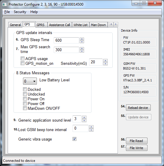
GPS Sleep time
Defines how frequently GPS is updating position while not controlled by other processes like tracking. Time interval can be set to: 0...65535 seconds (18:12:25 hrs) Default value is 600 (ten minutes). 0 means that GPS is permanently turned ON.
Max GPS search time
Defines for how long GPS is trying to get a refreshed position after receiving a position request. If the refreshed position is not acquired within that time, device sends position update using the previously stored last known position. Valid values for GPS search time are between: 120... 600 (seconds). Default value is 300 (five minutes). If the value is low, unit may not get position at all in poor satellite conditions. If the time is set long and unit is in poor satellite conditions it may unnecessarily increase power consumption and thus decrease operating time.
AGPS usage will determine whether AGPS (Assisted GPS) service is used. If the option is selected, unit will request assistance data from supporting server (same server as defined in setting GPRS IP address). Server must support TWIG AGPS service (For more information please contact [email protected]).
GPS_motion_on setting defines if the GPS is controlled by motion sensor. If selected, GPS is turned off to save battery whenever detected movement is lower than the value defined in the Sensitivity field. Note that if this option is selected, you cannot use Man Down alert functions.
Status messages
Define if the TWIG device transmits a message to Service Center informing of various events.
Device alerts when its battery level declines to 20, 40 or 60 percentage of full battery charge. Setting the value to 0 deactivates alarm. Default value is 0.
Note that battery levels can vary substantially when using the device, particularly when using timer functions. This may cause wrong or repeating Low Battery alarms.
Docked message is sent when TWIG Protector is placed in charging station CTA81 and Undocked message when picking up the device from charging station.
Power On message is sent when device is started and Power Off message when user turns off the device or it turns itself off due to low battery.
Note that if docking/undocking or power on/power off happen within 1 minute the latter status message may be lost.
ManDown ON/OFF send message if user toggles with ManDown function. This permission can be set in Man Down settings.
Generic application sound level
Defines the volume level that is used to play warning, notification and incoming call tones. Value can be set from 1 to 5, or if value 0 is used tones are not used at all. Default value is 3.
Lost GSM beep tone interval.
Defines the interval for BEEP tone in case the roaming GSM network is lost. You can set the interval between 20…65534 seconds. If set to 0, the tone will never be played. Default value is 0.
Generic vibra usage defines whether vibrator is used on generic notifications. A separate setting is for vibrator use in Emergency functions.
GPRS settings can be programmed remotely from the central station over MPTP SMS messages (as TWIG WebFinder SP does) or they can be programmed manually.
When GPRS settings have been programmed remotely, care must be taken not to interfere with remote settings when using TWIG Configurator.
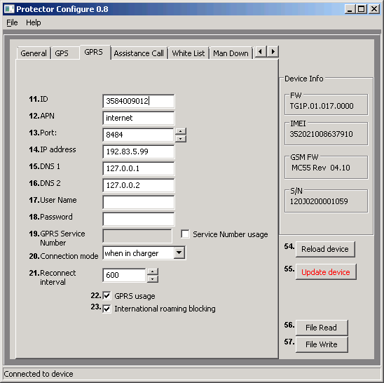
ID
User ID is a number used in identifying your phone in GPRS server. Typically this is the phone number of your TWIG device.
APN
The Access Point Name used for GPRS communication.
Define the entire APN value in the field. Typically GSM operators allow the APN to be left empty or replaced with “internet”. You can get the correct APN from your GSM operator.
GPRS server port number
A port number is required for GPRS communication. The value can be set between 0...65535. As default, TWIG Web Finder service port 8484 is used. In older firmware the default is locked. Contact TWIG Support if you need to change it.
GPRS IP address/domain
IP address that is used in GPRS communication. As default, TWIG Web Finder IP address 192.83.5.99 is used. In older firmware the default is locked. Contact TWIG Support if you need to change it.
TCP90EU with SW later than CT1?.010.021.0000 supports also domain name instead of IP address allowing flexibility.
GPRS DNS 1-2
Some GPRS networks require that primary domain name server (DNS1) is specified. Define the DNS as an IP address. Maximum length for DNS1 name is 16 characters. Default value for DNS1 is 127.0.0.1 and for DNS2 127.0.0.2.
GPRS user name
If your operator requires a user name for GPRS login, define the name here.
GPRS password
If your operator requires a password for GPRS log-in, define the word here.
Backup SMS number
Phone number where MPTP messages are sent as SMS, in case GPRS connection is not available, and Use SMS Backup if no GPRS is activated.
Some functionality changes or limitations may apply. For example, real-time tracking (TRR) is not possible via SMS.
Note that activating Backup SMS may result in high SMS transmission costs.
GPRS Connection mode
Defines how the GPRS connection to server is kept active:
0=only reconnect mode is used
1=always on when connected to charger, else reconnect mode
2=always on
Default=1
Note that if you define always on it may prevent device from sleeping or using timer functions. It also increases the power consumption significantly and thus reduces battery life.
Reconnect interval
Reconnect interval is used in reconnect mode. The device sends reconnect messages to server to check the server status and incoming messages possibly pending in server. You can set the sending interval for reconnect messages in seconds. Default value 600 s (ten minutes).
Note that if the value is set to 0 (zero), reconnect interval is not in use.
Reconnect Interval value is also used in timer based operations defined in Power Saving options.
GPRS usage
Defines if GPRS is used or not. 1 is enabled and 0 is disabled. Default=0.
Note that also user ID must be defined to use GPRS telematics.
GPRS international roaming blocking
If international roaming block is selected, GPRS connection is disabled when roaming outside home network. If not selected, GPRS connection is available also during international roaming.
Default value for international roaming blocking is inactive. The value is checked every time when creating GPRS connection.
Note that allowing GPRS data in roaming networks may result in very high data costs charged by your mobile operator. Unit may also roam in your own country close to country boarders.
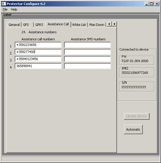
Assistance numbers
Here you define the action when the numeric keys on the TWIG Protector are pressed. If you program only one number per button the action is either call or MPTP assistance (!ASS) SMS depending on which is configured.
If both numbers are defined both actions are done.
In Protector Easy only first pair of numbers is used to trigger call/SMS with the Green SEND key.
In devices where there is no function e.g. Dog Locator or Asset Locator the fields have no value.
Programming “GPRS” as the SMS number the !ASS message will be sent over GPRS telematics.

White List is defining authorization of incoming SMS and/or voice call to perform automatic actions. If White List authorization is in use, the authorised numbers must be listed, otherwise messages and calls will be rejected.
WL Usage defines to which functions and how the White List is applied.
If disabled, White List is not used for authorising numbers. If SMS is selected all incoming MPTP SMS messages are screened. If CALL is selected all incoming calls are screened. If SMS and CALL is selected, incoming MPTP SMS and calls are screened.
Each White List number can be individually authorises to send location request and/or tracking activation SMS by checking the respective boxes.
Voice calls from each White List number can be individually screened:
Blocked: calls from this number are blocked
Allowed: calls from this number are allowed to ring
Auto answer: calls from this number are automatically answered
HF answer: calls from this number are automatically answered in hands-free (Speaker Phone) mode
Note that Speaker phone mode is very loud and its use must be carefully considered.
Automatic answer setting in General settings is overridden by White List when CALL or CALL and SMS is selected. A mix of allowed and blocked numbers can be defined, but if list has only blocked calls it blocks all calls.
GPRS messaging is not controlled by White List but by GPRS settings.
Note that regardless of White List settings the device can be reset to factory defaults by specific over-the-air commands (SMS or GPRS) when device particulars are known.
Note that if the GPS_motion_on setting is used, Man Down Alert can not be used and settings are greyed out.
Alerts when
Set the orientation which causes the sensor to launch Twig SOS.
When Horizontal is selected, Twig SOS is launched when device main axis orientation deviates from absolute upright position by more than Man down angle (in degrees).
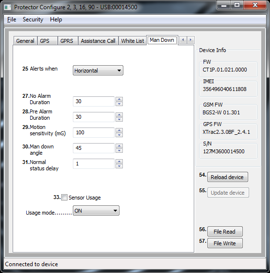
When Vertical is selected, Twig SOS is launched when device beam axis orientation deviates from absolute upright position more than Man down angle (in degrees).
Annex Man Down Angle illustrates device orientations for alert and no alert.
Default value is Horizontal.
Man Down Alert criteria combines Vertical/Horizontal detection with detection of movement. If the preferred alarm criteria is tilt angle only, then set Motion sensitivity (mG) to 999 (Alarm will be triggered by tilt angle as long as movement remains below 1 G).
When Movement is selected, only detected movement (acceleration) is monitored and device orientation does not affect launching of alert.
No alarm duration:
When the sensor detects alarm-triggering status (vertical/horizontal/no movement), this setting defines a waiting time during which the sensor is waiting for the normal status to be restored, before actually triggering the pre-alarm and finally alarm. This is useful to prevent unnecessary alarms for example in cases where the user has fallen down or sits down but is otherwise fine. No alarm duration can be set to 1 - 65535 seconds. Default value is 30 seconds.
Pre-Alarm duration:
Once Man Down sensor has detected an alarm-triggering condition and the No alarm period has passed, device enters Pre-Alarm period. During Pre-Alarm the user is alerted by sound and vibration (according to sound and vibration settings in SOS settings 2). When Pre-Alarm period is over, and normal orientation/movement has not been restored, Twig SOS is launched. Pre-Alarm duration can be set to 1 - 65535 seconds. Default value is 30 seconds.
Motion sensitivity:
This setting defines the amount of movement (acceleration) needed to indicate that the device is moving. Value can be set between 1 – 999 mG. Default value is 100 mG.
Man Down Angle
Defines the tilt angle (in degrees) the device must tilt, before its orientation is deemed to change from Vertical to Horizontal. Default value is 45 degrees.
Normal status delay
Normal status delay defines how long the device needs to be back in the normal orientation/movement before normal status is restored. Normal status delay is useful to prevent restoring the normal status and cancelling Twig SOS alert by accident. Normal status delay can be set 1 - 65535 seconds. Default value is 1 second.
Man Down sensor on/off]
Defines if the Man Down Alert is active or inactive.
Man Down sensor usage mode
Defines the mode how MDA is controlled.
ON= Man Down is always on when Protector is turned on.
Enabled on = MDA is turned on when Protector is turned on, but user can toggle mode off/on with key 4.
Enabled off = MDA is not turned on when Protector is turned on, but user can toggle mode on/off with key 4.

Phone Number and Name
Define SMS numbers to which alert MPTP messages are sent and voice numbers to which alert voice calls are made. Name is only for reference and not shown on screen. (Note that lines 1-10 on top correspond to lines 1-5 and 6-10 at bottom.)
Event type defines call or SMS. Event Retries defines how many times a failed event is retried before moving to next one. Event Group is not used.
All SMSs are sent first, at the same time as the first call (if any) is being made.
If GPRS connection to central station is defined, alarm MPTP message is sent over GPRS before making call. This does not delay the call more than a few seconds. If GPRS connection is not possible, call only will be made.
Because SMS transmission is in many circumstances more reliable than GPRS, it is recommendable to always define SMS for SOS message.
As soon as a call in the SOS event list is answered the cycle will stop making further calls, if Emg call continue (in SOS settings 2) is off. An answering machine will also stop making further calls. If Emg call continue is on, all calls in the SOS list will be made.
Note that to enable the GPRS emergency message the value “GPRS” ( without “”) must be written to the first “phone number” field
MPTP SOS Text
Defines the text in EMG message data field when TWIG SOS is initiated by SOS key. Default value is SOS BUTTON

MPTP MD Text:
Defines the text in EMG message data field when TWIG SOS is initiated by Man Down Alert. Default value is MAN DOWN ALERT
MPTP RF SOS Text:
Defines the text in EMG message data field when TWIG SOS is initiated by wireless alert button.
The three text fields above are 15 characters long maximum. They can only have characters 0-9, A-Z and a-z. No special characters are allowed.
Wireless alert unit serial number
Defines serial number of the Wireless alert button paired with the device. Maximum 5 buttons can be defined
When TWIG SOS is initiated by wireless alert button the EMG message includes text field (MPTP RF SOS Text) followed by wireless alert button index number (1 – 5).
Click on the Get RF ID button to activate learning mode. Then press the wireless alert button. Indicator on the button unit will first light red and turn green once paired.
To delete a wireless alert button, clear the corresponding Wireless alert unit serial number box and press enter. Then update device.
Vibrator enabled
Define if vibrator is used in conjunction with TWIG SOS. Device will vibrate when button is pressed and in case of Man Down Alert also during Pre-Alarm. Default is on.
Display enabled:
Defines if TWIG SOS is sent without showing actions on device screen. If disabled, only a small icon in the info line on top of screen indicates ongoing alert. This allows discrete or hidden TWIG SOS. Default is on.
Message resending,
Defines if the alarm message is resent if GPS position is refreshed during emergency cycle. Default is on.
Post emergency usage:
Defines if post emergency mode is active. This for example keeps GPRS connection on, blocks incoming calls and turns on post emergency beep to enable locating the user. If Post emergency mode is used another alarm can not be made until emergency mode is ended with RED END key. Default is on.
Power off disabled
Blocks the user from turning off the unit with power key. Default is off.
Emg call continue
Forces the emergency cycle to process all calls even if the preceding call is successful. I.e. all calls must be successfully made before stopping the emergency cycle.
Power up self test
Defines the self test for accessories, alarm button and Man Down. Can be used with or without requirement on ACK from ERC.
Poweroff when docekd
Defines if units is sending a request to power off when set to cradle. Power off is sent from ERC
Emergency number text
Defines the text for prompting user to call network emergency number, for example when no SIM card is inserted or no roaming network is available. Default text is 112.
Note that this is text only and does not affect dialling. Call will be made to public emergency service. No position is sent.
Post Emergency beep
Defines the time interval between “locate me” beeps. Range is 20 - 300 seconds. Default is 0 which means the beep is disabled.
SOS Activation mode
Selects how the TWIG SOS button is used to activate emergency cycle, between one long press or two presses.
Activation method timeout defines how long the SOS button needs to be pressed or within what time it needs to be pressed twice.
If SOS Activation mode is set as disabled, the button cannot be used.
Event Start delay
Defines a delay used between events in TWIG SOS cycle. Depending on the network this delay may need to be substantial since network may reject calls made in fast sequence. If there are only SMS numbers in the SOS cycle the delay can typically be shorter.
Full SOS Cycles
Defines the amount of full TWIG SOS event cycles to be done. Range is 1 – 5. Default is 1.
Call timeout
Defines the timeout to skip to next event on SOS list if no answer from B-subscriber.
Activation method timeout
Defines for how long the SOS button needs to be pressed or within what time it needs to be pressed twice. Default is 5 seconds.
Cancellation period
Defines the period (0..20 seconds) when the TWIG SOS can still be cancelled if activated from TWIG SOS button. Default is 0 which disables the cancellation possibility.
END Key Timeout
Defines if the TWIG SOS can be ended once started. 0 means it can only be ended from remote center by hanging up the call. Default is 1.
SOS tones sound level
Defines the warning and indication sound level used when starting TWIG SOS. Same setting is used for Pre-Alarm of Man Down Alert.
Speaker level
Defines the device speaker level when making a TWIG SOS call.
Note that levels 4..5 are on Speaker Phone level and are too loud for normal phone use.
EMG ACK timeout
Defines the time how long device will wait for acknowledgement from EMG message recipient before proceeding to next number in the list.
Mode
Defines if the operating mode of Amber Alert. Mode can be OFF, Local or Interactive. In Local mode no ACK is required to turn on the AA/CC. In Interactive mode ACK is required from activation number to turn on the mode.
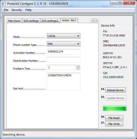
Phone number type
Defines if SMS or voice call is used to turn on the AA/CC mode.
Activation number
Defines the number where the activation SMS call is sent/made
Deactivation number
Defines the number where the deactivation SMS call is sent/made
PreAlarm time
Defines the timer value that is used to make prealarm when the AA/CC interval is met. During the PreAlarm user can either reset or turn off the AA/CC mode. If the mode is interactive ACK must be received from the Activation number before timer expires.
SOS Text
Defines the MPTP message text, that is send in !EMG message when Emergency Cycle is launched by AA/CC function.
Indoor module power on defines if the assembled module is turned on for use. Please note, that the module is not in all devices and it may also be deactivated so, that it can not be turned on. Please consult Twig Com Support if you think the module should be configurable, but there is no function.

Beacon low battery warning forwarding defines if the low battery information is sent from device to backend service. If the setting is on, the message is sent when device registers new beacon with low battery status. Low battery message is sent only once. When the device receives from same Beacon low battery cleared message the status of that Beacon low battery is reset.
RF tag enabled activates Protector to listen messages sent by RF Twig Tag.
Beacon search time defines the maximum time the Beacon signals are monitored.
SDR module sleep time. If the value is set to 0, the module is on all the time. Note that it effects the power consumption.
Internal MPTP command allows programming similar commands ready to device that typically are sent via SMS or GPRS. Such commands could be e.g. tracking or position request.
MPTP message can be sent automatically on every start up or when unit shifts from Emergency to Post Emergency mode.
As example automatic traking could be started when Emergency cycle is passed. The use of this mode requires, that post emergency is used in SOS Settings 2
If the usage mode is OFF the command will be processed automatically if mode is changed and the condition next time met.
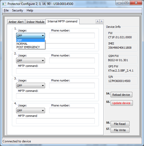
Usage field defines the condition when the command is executed.
Phone number is the recipient of SMS based MPTP message. MPTP command is the actual command that is processed
Updating software is done in TGP81EU under the Firmware tab. Device firmware is embedded in the TWIG Configurator program from version 1.2 onwards. If you have older version, please download the latest. Update your existing TWIG Protector software by clicking on the Burn -button. A progress bar displays the status of the updating process.
TCP90EU has separate program for only updating the FW. Please check www.twigcom.com.
You can save device settings from TWIG Configurator program to a PC file as well as read device settings files from PC to TWIG Configurator. As a default settings file is stored in the same directory where the actual TWIG Configurator program executable is stored. The default settings data file name is configure_save.bin. This file is used when the program is started and File read button is pressed.
By selecting File/Data FileName you can change the settings data file name. For example: Protector_settings_customer_A.bin.
Once defined, the same Data File will be used during one session, and any settings stored with File Write are stored there. Pressing File Read will bring the settings from that current Data File to program value fields and they can be then programmed to the TWIG device.
Note that you may need to change a value before the Update device button becomes active.
Different device types have different types of Firmware. The first 4 characters in the firmware file name define the type. Second and third set of numbers are version numbers and last set is custom version identifier.
A device cannot normally be programmed with firmware type different from the one already in the device. If you have a need to do so for example for testing please contact Twig Com Support at [email protected] or +358 40 510 5058
CG/T1P = TWIG Protector
CG/T1E = TWIG Protector Easy
CG/T1A = TWIG Asset Locator
CG/T1D = TWIG Dog Locator
Appendix A: Man Down Angles illustrated

CM52 NETWORK PROTECTORS PS024004EN FUNCTIONAL SPECIFICATION FOR CM52 NETWORK
CONVENIO DE COLABORACIÓN CON PROTECTORA MADRID DE
DEAR DHARMA PROTECTORS AND FRIENDS AS THE COLD WINDS
Tags: protector twig, twig protector, protector, asset, locator
- ARCHIVES OF ONTARIO PATHFINDER TO PRE1870 MARRIAGE REGISTRATIONS
- TEHNIČKI STANDARD HRTA ZA PRIHVAT AUDIOVIZUALNIH DJELA
- 10 UN LUGAR PARA DAR AMOR II POR
- FUNDACIÓN CENTRO DE ESTUDIOS AMBIENTALES DEL MEDITERRÁNEO BASES PARA
- PATIENT SAFETY MEASURES IN HEALTH CARE KNOWLEDGE ATTITUDE AND
- REFERAT FRA MØDE I RONETVÆRK NORDSJÆLLAND 15 APRIL I
- MINISTERSTVO FINANCÍ ODBOR 12 PID MFCR3XLKTR ČJ MF1001222013121203 REFERENT
- 20141217 KUNGÖRELSE DNR LIU201402025 2(2) BIDRAG TILL FORSKARSTUDERANDE POSTDOKTOR
- TREEWALKS 1 2 3 A GUIDE TO THE ARBORETUM
- SBĚRNÝ DVŮR I PRO OKOLNÍ OBCE ROZŠÍŘENÍ MOŽNOSTI UKLÁDÁNÍ
- 5 PROGRAM K ZAJIŠTĚNÍ BEZPEČNOSTI POSKYTOVANÝCH STRAVOVACÍCH SLUŽEB UPOZORNĚNÍ
- INSTRUKCJA ZWROTU OPŁAT REKRUTACYJNYCH ZWROT OPŁAT REKRUTACYJNYCH 1 WNIOSKOWAĆ
- WYMAGANIA EDUKACYJNE NA POSZCZEGÓLNE OCENY Z JĘZYKA POLSKIEGO W
- ÉCOLE NATIONALE SUPÉRIEURE VÉTÉRINAIRE DÉPARTEMENT CLINIQUE EMD2 ANNÉE UNIVERSITAIRE
- REVISIÓN DINÁMICA DEL MOVIMIENTO DE CAÍDA LIBRE CONCEPTOS DE
- CULTURE OF DISCRIMINATION A FACT SHEET ON “HONOR” KILLINGS
- M EDIA CREDENTIALS APPLICATION 2018 RICHMOND JAZZ FESTIVAL RICHMONDJAZZFESTIVALCOM
- C GUTIÉRREZ SOLANA 39 39600 MALIAÑO (CANTABRIA) TLF 942
- Healthy Fathering Collaborative Sponsored by Community Endeavors Foundation inc
- POWER OF ATTORNEY AND AUTHORIZATION EXACT NAME OF
- BROJ 01111305721 SARAJEVO30042021 GODINE NA OSNOVU ČLANA 100 STAV
- ANDALUCÍA MUNICIPIO NOMBRE PROYECTO INICIATIVA GESTIÓN PARCELAS SUPERFICIE PARCELA
- INTESTAZIONE AL SINDACO DEL COMUNE DI POLLONE PIAZZA VINCENZO
- UNIVERSIDAD DE BUENOS AIRES FACULTAD DE FILOSOFIA Y LETRAS
- GY 111 METAMORPHIC ROCKS KEY ROCK NAME MINERALS
- PC GÜMRÜK KÜLLIYATIWWWARSLANNETCOM HER TÜRLÜ BOŞ VİDEO KASETİ SES
- SALARY AGREEMENT AND VENDOR ALLOCATION FORM ALTERNATE BENEFIT
- BURIAVIMO REGATOS VARŽYBOS LSD „ŽALGIRIS“ PRIZAMS LAIMĖTI NUOSTATAI 2021
- R EGULAMIN GMINNEGO KONKURSU ORGANIZATOR KONKURSU ŁABISZYŃSKI DOM KULTURY
- DIBUJO TÉCNICO – CUERPOS SÓLIDOS PRISMASPIRÁMIDESCONO ESFERA 2º
 PATVIRTINTA PRIEŠGAISRINĖS APSAUGOS IR GELBĖJIMO DEPARTAMENTO PRIE VIDAUS REIKALŲ
DID YOU GET SUED AND ARE THINKING ABOUT FILING
BESF2040PL 20’ X 40’ SOLID SURFACE BATTER’S EYE
MARKETING FONDAMENTAL LICENCE AGE UNI PARIS XII
A MAGYAR KÖZTÁRSASÁG BELÜGYMINISZTERÉNEK AZ OSZTRÁK KÖZTÁRSASÁG SZÖVETSÉGI BELÜGYMINISZTERÉNEK
A BANK CRISIS IN A BANKCENTERED FINANCIAL SYSTEM
 ……………… MÜDÜRLÜĞÜ DOKÜMAN NO 91800PL08 YAYIN TARIHI 01082020 REVIZYON
 MEMÒRIA TÈCNICA DEL PEBRE (CAPSICUM SPP) DEL CATÀLEG DE
ADATVÉDELMI TÁJÉKOZTATÓ ÖRÖKBE FOGADNI SZÁNDÉKOZÓ HÁZASPÁROKNAK AZ EGYÜTT AZ
 ALLENS CROSS WARD PLAN 2018 2022 CONTENTS ITEM
AUCTION NO 14 29 SEPTEMBER – 1 OCTOBER 2005
PDP ROEHAMPTON UNIVERSITY GRADUATE SCHOOL RESEARCH STUDENT PERSONAL DEVELOPMENT
 MADRID 11 DE DICIEMBRE 2007 ASUNTO FERIA INTERNACIONAL DE
APUNTES EL VERBO “ESTAR” ESTAR YO NOSOTROSAS TÚ
 FOLHA 01 ADAF AGÊNCIA DE DEFESA AGROPECUÁRIA E FLORESTAL
sj Czinn Curriculum Vitae p 31 Steven j Czinn
COMPENDIO DE CÓMO DEPOSITAR TÁCTICAMENTE ORGONITO (GIFTING) 18 DE
 EXPOSICIÓN Y ANÁLISIS DE LAS REFORMAS INTRODUCIDAS POR LA
DANIEL GONZÁLEZ DE LA PEÑA TESORERO DE AESLEME BREVE
DKKZY KKI 1068XXVIII&2&2009&372009] FNUKAD 30 FLRECJ] 2009 DK LAYXUD
