A UNIQUE FORM FOR COPPER INFILTRATION – WROUGHT WIRE
COMMMUNIQUE DE PRESSE RUBRIQUES10 TRANSCENDING OURSELVES THE BOARD’S UNIQUE CONTRIBUTION TO
20 ABORIGINAL PEOPLE WITH DISABILIY UNIQUE APPROACHES TO UNIQUE
A COORDINATE SYSTEM IS USED TO UNIQUELY DETERMINE THE
A FULLY LITERATE SOCIETY A UNIQUE VISION FOR SCOTLAND
A UNIQUE FORM FOR COPPER INFILTRATION – WROUGHT WIRE
Speaker:
A UNIQUE FORM FOR COPPER INFILTRATION – WROUGHT WIRE INFILTRANT
Howard Sanderow* and Paul Rivest**
*Management & Engineering Technologies
Dayton, OH 45415
**Ultra Infiltrant
Carmel, IN 46033
ABSTRACT
As the PM industry continues to investigate new higher performance materials and processes, a re-examination of the copper infiltration process for high strength, as-sintered products is introduced using a new infiltrant form. A wrought copper alloy wire product has been shown to offer an excellent infiltration response for the FX-1008 copper infiltrated steel grade. A complete set of mechanical properties for several levels of infiltrant and skeletal densities are provided. Very high infiltrated densities (greater than 7.7 g/cm3) were achieved for this 15% maximum copper grade. Comparisons are drawn with conventional compacted powder infiltrants as well as the properties reported in MPIF Standard 35 for this alloy. The advantages of using this wrought wire form for the copper infiltration process are also presented.
INTRODUCTION
Copper infiltration of porous ferrous compacts, also known as the iron matrix or skeleton, has been popular in the North American market for over 60 years as a method to reduce the porosity and increase the strength of PM steel components. In this process the porous ferrous compact is brought into intimate contact with a copper base alloy and the two components are sintered at a temperature whereby the copper alloy melts and infiltrates the porosity of the ferrous compact [Ref 1, 2, 3, 4]. The ferrous compact may be in the green or sintered condition. If in the green condition this process is known as one-step infiltration or “sintration”. While better dimensional control is typically associated with the two-step infiltration process (sinter the ferrous compact first and then infiltrate) the one-step process is most popular for its lower processing cost. The copper infiltrant typically has been a specially formulated copper powder material compacted into the shape of a disc, wafer, slug or ring, suitably placed on the top or underneath the ferrous compact during sintering. The assembly is placed on a sinter tray, typically a graphite plate, to support the assembly and prevent molten copper from possibly dripping on the sintering belt and causing damage.
The molten copper is drawn into the interconnected pores of the ferrous matrix by capillary action. The capillary pressure varies inversely with pore diameter and indirectly with the surface energy of the infiltrating liquid and the contact angle. Therefore the infiltrating alloy should be designed to have good wettability and fluidity, low surface energy (limited solubility of the two materials or formation of an intermediate phase). Since smaller pores have greater capillary force these are filled first and more completely than larger pores.
When there is some mutual solubility of the matrix into the infiltrant, as in the case of iron and copper, the infiltrant composition is modified to limit the dissolution of the matrix by matching the equilibrium composition of the infiltrant to that of the matrix at the infiltrating temperature. Most commercial powdered infiltrants contain several weight percent iron to minimize erosion during infiltration. In addition it is generally desirable to limit the effects of the mutual solubility by keeping the infiltration time period short and the infiltration temperature sufficiently low. Finally it is extremely important that the surface of the ferrous matrix be clean, oxide-free and soot-free to ensure proper wetting by the molten infiltrant.
Ferrous PM components are copper infiltrated in order to improve physical or mechanical properties as noted below [Ref. 1].
Tensile strength, ductility and impact resistance
Improved machinability
Improved thermal conductivity
Provide pressure tightness for leak-free operation in hydraulic applications
Seal porosity for secondary operations such as plating
Selective property improvement through localized infiltration
Few material or process developments have been reported in the field of copper infiltration for nearly 20 years, since the flurry of patents by SCM in the period 1986-1990 [Ref. 5]. Yet in 2005 several new products were introduced. One powder manufacturer introduced several powder infiltrant compositions for use specifically with higher density PM steel performs [Ref. 6]. Another introduced a paste infiltrant for use in valve seat insert ring applications [Ref. 7]. One PM parts producer returned to pure copper in sheet form as a possible answer to certain infiltration problems [Ref. 8].
Why a Wrought Form Copper infiltrant?
Commercial copper infiltrating powders typically consist of >90% by weight copper, approximately 2-5% iron, and several proprietary additives, such as zinc and manganese. In some cases the powder is completely or partially prealloyed while in others the additions can be elemental powders. Many of the powder infiltrants form a non-adherent residue during infiltration as a means to hold the molten copper in place during infiltration, preventing the molten copper from running off the edge of the component. Any excess infiltrant caused by process weight variation is retained in the residue. A few powder infiltrants do not form a residue and therefore require closer control of the infiltration conditions, especially part and infiltrant weight as well as infiltrating temperature.
The new wrought copper alloy wire infiltrant eliminates many of the process variations associated with powder copper infiltrants. The product is fully prealloyed, thereby eliminating any possibility of the elemental powder additives segregating during powder transport, storage or die filling. The infiltrant preforms are supplied cut to length or coiled for precise size and weight control for ease of placement with the ferrous matrix. The rigid wrought infiltrant preforms allow for ease of handling, precise placement and 100% product usage. Problems with the fragile, easily fractured or damaged powdered infiltrant are eliminated, cutting the scrap rate to zero.
In addition to the processing issues described above the new wrought copper infiltrant eliminates the need for a separate set of tools to press the infiltrant as well as the press to compact the infiltrant and the personnel to monitor and handle the fragile powdered infiltrant. Storage and transport of these delicate compacted infiltrant performs is also removed from the processing route, replaced by a robust, rigid, easily handled wrought wire infiltrant.
OBJECTIVE
The goal of this investigation was to determine the physical and mechanical response of the new wrought wire form copper infiltrant as compared to commercial powdered infiltrants and the properties reported in MPIF Standard 35 for the FX-1008 copper infiltrated steel grade.
EXPERIMENTAL PROCEDURE
Three investigations were conducted to characterize the wrought wire form copper infiltrant. The initial study selected one iron powder noted for its excellent copper infiltration response which was compacted at two green densities and one level of wrought wire infiltrant. The wrought wire infiltrant was provided by Ultra Infiltrant. The iron matrix was compacted at 6.65 g/cm3 and 6.95 g/cm3 using QMP Atomet 28 iron powder blended with 0.9% Southwest 1651 graphite and 0.75% Acrawax C lubricant. Five tensile, TRS and Charpy impact test specimens, conforming to MPIF Standards 10, 41 and 40, were prepared using the iron powder blend. The wire infiltrant was placed on top of the green specimens and then processed using a one-step sinter-infiltration process in a commercial mesh belt sintering furnace at 1125°C (2060°F) with 90% nitrogen -10% hydrogen atmosphere.
The second study changed the iron matrix to the QMP Atomet 1001 atomized steel powder with 0.8% Southwest 1651 graphite and 0.75% Acrawax C lubricant. In this experiment the matrix green density was 6.7 g/cm3. In addition to investigating the Ultra Infiltrant wire form infiltrant, this study included a commercial, residue-free powdered infiltrant. This powdered infiltrant was compacted at 415 MPa (30 tsi). The test specimens were limited to five TRS bars per MPIF Standard 41 for each experimental condition. The infiltrant was again placed on the top of the test bars and sintered in the same commercial sintering furnace using the same sintering conditions as the first set of samples.
The third study compared the Ultra Infiltrant wire form infiltrant to a second commercial powdered infiltrant. This study returned to the QMP Atomet 28 base powder mix used in the first study. The amount of wire infiltrant was extended to a lower and higher amount in order to determine the range of useful operation for the new infiltrant. The iron matrix was compacted to a green density of 6.7 g/cm3 and 6.95 g/cm3 green density using five TRS, tensile and Charpy impact specimens which conformed to MPIF Standard 41, 10 and 40 for each test condition. The commercial powdered infiltrant #2 (also a residue-free grade) was compacted at 415 MPa (30 tsi). The infiltrant was placed on top of the iron matrix specimens and sintered in the same commercial sintering furnace using the same processing conditions as the first study.
Mechanical properties (tensile, TRS, hardness and impact energy) and final dimensions were measured for each test specimen in the infiltrated condition with no effort to clean or abrade the specimen surface. Optical microscopy was used to characterize the microstructure of the wire infiltrated materials. An SEM/EDS analysis characterized the two infiltrant materials – the wire infiltrant versus the powdered infiltrant #2.
RESULTS
Study #1 – Initial Investigation
The results of the initial investigation listed in Table 1 reflect the F-0008 base iron matrix using QMP Atomet 28 iron powder and the wire infiltrant, which results in a composition that conforms to MPIF Standard 35 copper infiltrated steel grade FX-10008. Standard values for the FX-1008 grade are included in Table 1 for comparison to the test results.
Table 1 – FX-1008 Using Wire Infiltrant and QMP Atomet 28 Iron Matrix
|
Green Density g/cm3 |
% Infiltrant |
Infiltrated Density g/cm3 |
Tensile Strength MPa (psi) |
Yield Strength MPa (psi) |
Elongation
% |
TRS
MPA (psi) |
Hardness
|
Impact Energy (J) (ft-lbs) |
|
6.65 |
14.5 |
7.55 |
790 (114,000) |
590 (86,000) |
2.7 |
1480 (215,000) |
21 HRC |
15 (11) |
|
6.90 |
13.5 |
7.70 |
880 (127,000) |
650 (94,000) |
3.0 |
1510 (219,000) |
27 HRC |
16 (12) |
|
MPIF Std 35 FX-1008-50 |
7.3 |
600 (87,000) |
410 (60,000) |
3.0 |
1140 (166,000) |
89 HRB |
14 (10) |
|
The test results find the new infiltrant to be very effective in strengthening the iron matrix using both a medium and high density iron matrix. The higher matrix density results demonstrate the benefit of using a higher density matrix for increased strength and hardness. No improvement in ductility or impact resistance was noted at this higher density. Both results far exceeded the strength values listed in MPIF Standard 35 for the FX-1008 grade with the lower density matrix results 30% higher than the values listed in Standard 35 and the higher density matrix 50% stronger.
The microstructure of these two materials is shown in Figures 1-3. Figure 1 illustrates the unetched structure of the medium density matrix with an infiltrated density of 7.55 g/cm3. The upper left view is the top surface (infiltrant placement surface), the lower left view about one-third through the part thickness, the upper right view about two-thirds through the part thickness and the lower right view the bottom of the specimen (0.24 inch thick). The material is well-infiltrated with only the very largest pores not filled with infiltrant. Image analysis of these four areas measured 4.3%, 7.5% 8.8% and 6.9% porosity in these regions, demonstrating the uniformity of the infiltration process using the wire infiltrant.
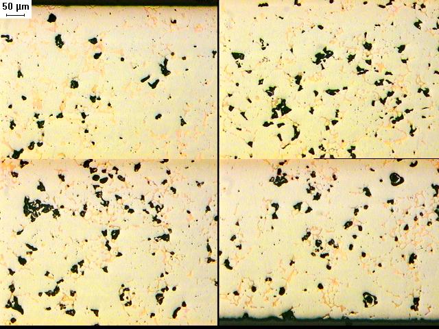
Figure 1. Photomicrographs illustrate the unetched structure of the 6.7 g/cm3 density iron matrix with an infiltrated density of 7.55 g/cm3. The upper left view is the top surface (infiltrant placement surface), the lower left view about one-third through the part thickness, the upper right view about two-thirds through the part thickness and the lower right view the bottom of the specimen.
Figure 2 illustrates the unetched structure of the high density matrix with an infiltrated density of 7.8 g/cm3. The four views follow the same position through the thickness of the sample as described previously for Figure 1 – upper left is the top surface, lower right is one-third through the thickness, upper right is two-thirds through and the lower right view is the bottom of the sample. The material is nearly fully infiltrated with only a few isolated pores unfilled. Image analysis of these four areas measured 0.7%, 2.5%, 2.8% and 1.8% porosity in these four regions, demonstrating the effectiveness of the wire infiltrant for filling nearly all the open porosity of the high density iron matrix.
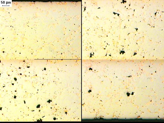
Figure 2. Photomicrographs illustrate the unetched structure of the 6.95 g/cm3 density iron matrix with an infiltrated density of 7.8 g/cm3. The upper left view is the top surface (infiltrant placement surface), the lower left view about one-third through the part thickness, the upper right view about two-thirds through the part thickness and the lower right view the bottom of the specimen.
Figure 3 illustrates the etched structure of the two materials – the two left hand views are the medium density matrix material while the two right hand views illustrate the high density matrix material. Both materials show a 100% pearlite microstructure (top views 125X, bottom views 800X) with copper infiltrant uniformly dispersed in the matrix.

Figure 3. Photomicrographs illustrate the etched structure of the two materials from Study #1 – the two left hand views show the 6.7 g/cm3 density iron matrix; the two right hand views show the 6.95 g/cm3 density iron matrix material. The structure is 100% pearlite (top views 125X, bottom views 800X) with copper infiltrant uniformly dispersed in the matrix porosity.
Study #2 – Investigation of Water Atomized Steel Powder Matrix
The results of the second investigation listed in Table 2 reflect the F-0008 base iron matrix using QMP Atomet 1001steel powder infiltrated with the wire infiltrant and a commercial powdered infiltrant, which resulted in a composition that conforms to MPIF Standard 35 copper infiltrated steel grade FX-10008. Standard values for the FX-1008 grade are included in Table 2 for comparison to the test results.
Table 2 – FX-1008 Using Wire Infiltrant and QMP Atomet 1001 Steel Matrix
|
Infiltrant |
Green Density g/cm3 |
% Infiltrant |
Infiltrated Density g/cm3 |
TRS MPa (psi) |
Hardness
HRB |
|
Wire |
6.7 |
11.3 |
7.33 |
1530 (222,000) |
94 |
|
Powdered #1 |
6.7 |
13.6 |
7.38 |
1450 (210,000) |
90 |
|
MPIF Std 35 FX-1008-50 |
7.3 |
1140 (166,000) |
89 |
||
The test results find the wire infiltrant just as effective in strengthening the steel matrix as the commercial powdered infiltrant, using 17% less infiltrant. Both infiltrant results far exceeded the transverse rupture strength values listed in MPIF Standard 35 for the FX-1008 grade. The infiltrated hardness values were comparable for the two infiltrants and the standard value.
Study #3 – Extended Investigation of QMP Atomet 28 Iron Matrix
The results of the third investigation listed in Table 3 reflect the F-0008 base iron matrix using QMP Atomet 28 iron powder, the wire infiltrant and a second commercial powdered infiltrant #2. The final composition again conforms to MPIF Standard 35 copper infiltrated steel grade FX-10008. Standard values for the FX-1008 grade are included in Table 3 for comparison to the test results.
Table 3 – FX-1008 Using Wire Infiltrant, Powdered Infiltrant #2 and QMP Atomet 28 Iron Matrix
|
Green Density g/cm3 |
% Infiltrant |
Infiltrated Density g/cm3 |
Tensile Strength MPa (psi) |
Yield Strength MPa (psi) |
Elongation
% |
TRS
MPa (psi) |
Hardness
|
Impact Energy (J) (ft-lbs) |
|
6.7 |
10.9 |
7.45 |
790 (114,000) |
630 (91,000) |
2.0 |
1290 (187,000) |
92HRB |
20 (14) |
|
6.7 |
14.0 |
7.60 |
830 (120,000) |
630 (91,000) |
1.3 |
1340 (195,000) |
28 HRC |
15 (11) |
|
6.95 |
10.8 |
7.65 |
850 (123,000) |
660 (96,000) |
1.3 |
1430 (207,0000) |
28 HRC |
18 (13) |
|
6.95 |
14.3 |
7.80 |
850 (123,000) |
680 (98,000) |
1.2 |
1490 (216,000) |
32 HRC |
15 (11) |
|
|
|
|
|
|
|
|
|
|
|
6.7
|
Powder 13.5 |
7.45 |
810 (117,000) |
620 (90,000) |
1.0 |
1300 (189,000) |
25 HRC |
16 (12) |
|
|
|
|
|
|
|
|
|
|
|
MPIF Std 35 FX-1008-50 |
7.3 |
600 (87,000) |
410 (60,000) |
3.0 |
1140 (166,000) |
89 HRB |
14 (10) |
|
The test results find the new infiltrant to be very effective in strengthening the iron matrix using both a medium and high density iron matrix, and using a medium and high level of infiltrant within the FX-1008 composition range. The medium density matrix using the 10.9% wire infiltrant provided mechanical properties equivalent to the powdered infiltrant #2 at 13.5% infiltrant and 30% stronger than the values listed in MPIF Standard 35. Increasing the amount of wire infiltrant from 10.9% to 14.0% increased the infiltrated density to 7.6 g/cm3 but had limited effect on strength, ductility or impact resistance when using the 6.7 g/cm3 matrix density. Increasing the matrix density from 6.7 g/cm3 to the high density matrix of 6.95 g/cm3 further increased the infiltrated density but again had no significant effect in raising strength or hardness or impact resistance.
The combination of the 14.3% wire infiltrant with the 6.95 g/cm3 density matrix exceeded the maximum amount of copper infiltrant that could be absorbed in the pore structure of the matrix. Small pools of molten copper were found solidified on the surface of the test bars. The acceptable results from Study #1 at 13.5% wire infiltrant but excess infiltrant at the 14.3% level from Study #3 identifies 14% infiltrant as the maximum amount of wire infiltrant that can be accommodated in the 6.95 g/cm3 matrix when using the QMP Atomet 28 based F-0008 composition.
The dimensional change from die size results from study #1 and study #3 using the QMP Atomet 28 iron matrix and the wire infiltration product are summarized in Table 4.
Table 4 – FX-1008 Using Wire Infiltrant and QMP Atomet 28 Iron Matrix
|
Matrix Green Density g/cm3 |
% Infiltrant |
Infiltrated Density g/cm3 |
Dimensional Change % |
|
6.65-6.70 |
10.9 |
7.45 |
+0.32 |
|
|
14.0 |
7.60 |
+0.36 |
|
|
14.5 |
7.55 |
+0.29 |
|
|
|
|
|
|
6.90-6.95 |
10.8 |
7.65 |
+0.40 |
|
|
13.5 |
7.70 |
+0.42 |
|
|
14.3 |
7.80 |
+0.48 |
The dimensional change from die size was quite consistent for a given matrix green density, even as the amount of wire infiltrant was increased 40%. For the higher matrix density the dimensional growth increased very slightly as the amount of infiltrant was increased. In general the higher the matrix green density the greater the dimensional growth during infiltration.
Comparison of Wire Infiltrant and the Powdered Infiltrant #2
In order to understand the differences in the infiltration response when using the wrought wire versus the powdered infiltrant the SEM/EDS analysis method was used to compare the alloy homogeneity of the wire infiltrant to the powdered material. The four major alloying elements identified in each material were copper, iron, zinc and manganese. The EDS spectra of these elements found a homogeneous and uniform distribution throughout the wire sample, as expected from a melted wrought material. In contrast the powdered material was extremely non-homogeneous. Figure 4 illustrates a typical random view of the powdered infiltrant. The powder consisted of four or five different types of particles – (a) round, globular solidified particles, (b) larger, textured irregular particles, (c) small irregular particles, (d) flat, striated particles and (e) small flake-like particles. By use of the EDS system the characteristic spectra of the three alloying elements were found to be isolated relative to specific particles in the powder and not homogeneous throughout the powder mass. For instance, manganese was identified with the flat striated particle seen in the middle of Figure 4 (identified as particle #1) and iron was identified with an irregular particle identified at the extreme bottom of Figure 4. The bulk of the particles were either pure copper or a copper-zinc alloy (prealloyed brass powder), identified as particle #2 or particle #3 in Figure 4. Following this SEM/EDS analysis a small magnet was placed in a sample of powdered infiltrant #2. Upon withdrawal of the magnet the tip was coated with fine grey particles aligned with the magnetic field of the magnet’s tip, indicating the presence of unalloyed iron powder particles in powdered infiltrant #2.

Figure 4. SEM photomicrograph of a typical portion of powdered infiltrant #2 showing the variety of powder particles (sizes and shapes) in the powdered infiltrant.
DISCUSSION
The mechanical properties of the wire infiltrated FX-1008 material were somewhat dependent on the density of the iron matrix but were adequately developed at an infiltrant level as low as 10.9%. Additional infiltrant, in excess of 13.5% was not necessary to develop the maximum mechanical properties, e.g. tensile strength or impact resistance. The additional infiltrant was only needed to provide a near fully dense microstructure, as required for pressure tightness. An infiltrated density in excess of 7.7 g/cm3 was achieved using the higher density iron matrix (6.95 g/cm3) and 13.5% infiltrant and an infiltrated 7.6 g/cm3 density when using the medium density (6.7 g/cm3) matrix. In contrast, the powdered infiltrant only reached a density of 7.45 g/cm3 when using the 6.7 g/cm3 matrix density.
The dimensional change data finds the wire infiltrant extremely consistent, even when the amount of infiltrant varies by several weight percent. The dimensional consistency varied only slightly (+0.10% more growth) when the matrix density increased from 6.7 to 6.95 g/cm3.
A significant variable in this study was the effect of the matrix iron/steel powder. The Atomet 28 powder was a much more effective and easily infiltrated ferrous powder than the more widely used water atomized steel powder. While the strength achieved using the two matrix powders was identical the final density was much higher using the Atomet 28 powder. For applications requiring pressure tightness a lower amount of infiltrant is necessary when using the wire infiltrant and the Atomet 28 matrix combination.
When comparing the wire infiltrant to the conventional powdered infiltrant the amount of infiltrant needed to reach a given strength level is 15-18% less than when the wire infiltrant product is selected. As noted in Table 3, the wire infiltrant at 10.9% infiltrant reached 790 MPa tensile strength and 20 J impact energy while the powdered infiltrant required 13.5% infiltrant to reach a similar strength (810 MPa tensile strength) and only 15 J impact energy. The difference in mechanical response and infiltration efficiency between the two infiltrants may be related to the homogeneity of the wire infiltrant versus the powdered material as well as the non-productive portion of the powdered infiltrant (the admixed lubricant and the residue formed during infiltration).
Differences in the infiltration response between the wire infiltrant and the conventional powdered infiltrant may be related to the homogeneous nature of the wire versus the mixed powders used to formulate the powdered infiltrant. During the melting of the copper portion of the powdered infiltrant at the infiltrating temperature the admixed manganese and iron can easily segregate and remain on the surface of compact, forming the basis of the residue. With little of the iron powder dissolved in the molten copper there is increased likelihood for erosion.
CONCLUSIONS
1. The wire infiltrant provides a more effective infiltration response than the conventional powdered infiltrant, providing equivalent mechanical properties when using 15-19% less infiltrant.
2. The wire infiltrant provides a higher infiltrated density for the same amount of infiltrant (no loss due to residue or lubricant).
3. The wire infiltrant can achieve a 7.8 g/cm3 infiltrated density with 14% infiltrant using a 6.95 g/cm3 dense skeleton.
4. The dimensional change response of the wire infiltrant was very consistent within the range of infiltration parameters for this study (amount of infiltrant and density of the matrix).
5. The homogenous, prealloyed nature of the wrought wire infiltrant provides a more consistent and effective infiltration response as compared to the mixture of powders found in the conventional powdered infiltrant.
REFERENCES
1. P. Samal and E. Klar, “Copper-Infiltrated Steels”, Powder Metal Technologies and Applications, ASM Metals Handbook - Volume 7, 1998, ASM International, Materials Park, OH, p. 769-773.
2. F. V. Lenel, Powder Metallurgy-Principles and Applications, 1980, MPIF, Princeton, NJ, p. 316-317.
3. R. M. German, Powder Metallurgy Science, 2nd Edition, 1994, MPIF, Princeton, NJ, p. 310-312.
4. L. F. Pease, III and W. G. West, Fundamentals of Powder Metallurgy, 2002, MPIF, Princeton, NJ, p. 159-162.
5. US Patent # 4,606,768; 4,769,071; 4,921,665; 4,861,373; 4,976, 778.
6. J. Joys and S. Luk, “Infiltration of Ferrous P/M Compact with Copper Infiltrants”, Advances in Powder Metallurgy and Particulate Materials-2005, compiled by C. Ruas and T. A. Tomlin, MPIF, Princeton, NJ, 2005, Volume II, Part 6, p. 82-95.
7. M. K. Barr, A. V. Nadkarni and G. L. Cowan, “Infiltration of Ferrous P/M Parts with Infiltrating Paste”, Advances in Powder Metallurgy and Particulate Materials-2005, compiled by C. Ruas and T. A. Tomlin, MPIF, Princeton, NJ, 2005, Volume II, Part 6, p. 96-106.
8. K. Byrd, “An Investigation of Alternative Copper Infiltration Techniques”, Advances in Powder Metallurgy and Particulate Materials-2005, compiled by C. Ruas and T. A. Tomlin, MPIF, Princeton, NJ, 2005, Volume II, Part 6, p. 107-114.
ABOUT JUNCTION JUNCTION ARTS FESTIVAL (JAF) IS A UNIQUE
ABSTRACTS FOR CYBER CRIME SUMMIT KEYNOTES CYBERCRIME A UNIQUE
ADOLESCENT INVULNERABILITY AND PERSONAL UNIQUENESS SCALE DEVELOPMENT AND INITIAL
Tags: copper infiltration, alternative copper, copper, wrought, unique, infiltration
- A TIPOGRÁFIA ALAPJAI A TIPOGRÁFIA SZÓ GÖRÖG EREDETŰ
- ZMIANA NR 2 ZAPROSZENIA DO ZŁOŻENIA OFERTY O WARTOŚCI
- LOCAL FIREFIGHTERS PENSION BOARD FRIDAY 9 OCTOBER 2020 AT
- OPTICAL MOUSE WITH VOIP TELEPHONE FUNCTION SKYM1 OPTICAL MOUSE
- EINGANGSVERMERK DER BEHÖRDE DATUM AZ ABSENDER LANDESVERWALTUNGSAMT DES
- IN DE VORIGE BIJDRAGE IN DIT BLAD IS KORT
- OSE BUDGET WORKSHEET OFFICE OF THE STATE ENGINEER 523
- EXTENDAGUN BRACKET SET TASK FORCE TIPS MODEL XGB33
- ZAŁĄCZNIK NR 8 DO SIWZ OPIS RZEDMIOTU ZAMÓWIENIA 1
- 1 AWARDING INSTITUTION THE ROYAL VETERINARY COLLEGE 2 TEACHING
- GUÍA PARA LA EXPORTACIÓN OCASIONAL DE MUESTRAS BIOLÓGICAS PARA
- EQUAL INCHES PURPOSE 1 STUDENTS WILL BEGIN MEASURING WITH
- WNUG WNIOSEK OSOBY NIEPEŁNOSPRAWNEJ WYKONUJĄCEJ DZIAŁALNOŚĆ GOSPODARCZĄ O WYPŁATĘ
- A PROFESSIONAL LAW CORPORATION OAKLAND LOS ANGELES SACRAMENTO SAN
- EL C LIC HÉCTOR ISRAEL CASTILLO OLIVARES PRESIDENTE MUNICIPAL
- PM’S CLOSING REMARKS WE HAVE HAD A VERY FULL
- „GRÜNDE UND RÄUMLICHE ERSCHEINUNGSFORMEN DER TRANSFORMATIONSVORGÄNGE IN RUSSISCHEN STÄDTEN“
- Reportaż Jest Gatunkiem o Rodowodzie Publicystycznym Sprawozdanie z Wydarzeń
- BIENES DE CAPITAL INFORMÁTICA Y TELECOMUNICACIONES SE MODIFICA LO
- OBJETIVOS GENERALES DE ETAPA LOS OBJETIVOS ESTABLECEN LAS CAPACIDADES
- MEMÒRIA SOBRE LA VALORACIÓ DE LLOCS DE TREABALL LLIURAT
- FIRST ET AL | 3 9TH INTERNATIONAL WORKSHOP ON
- SUPPLEMENTAL MATERIAL FOR AN ALTERNATIVE EXPLICIT MODEL EXPRESSION EQUIVALENT
- PIANO FORMATIVO INDIVIDUALE PFI RELATIVO ALL’ASSUNZIONE DELLA SIGRA
- ARBEIDSDOKUMENT HUNDREÅRSFESTIVALEN I OSLO 010505 HVA
- THE DESCRIPTION OF A LECTURER‘S PROFESSIONAL PERFORMANCE 1 NAME
- UNIVERSITY OF LIMERICK OLLSCOIL LUIMNIGH CONFLICTS OF INTEREST PROTOCOL
- PATVIRTINTA VENTOS REGIONINIO PARKO DIREKTORIAUS 2017 M VASARIO 1
- ORZECZNICTWO SN I SĄDÓW INSTANCYJNYCH DOTYCZĄCE ZASKARŻANIA UCHWAŁ ORGANÓW
- Cvca Venture Capital Model Transaction Documents Management Rights
I STYLE ANALYSIS A DICTION – WORD CHOICE INTENDED
 INTERVIEW GUIDE KKN ETNOGRAFI PEDOMAN WAWANCARA DAN OBSERVASI 1
DISTRIBUCIÓN DE ESTÁNDARES EN LOS DIFERENTES TRIMESTRES ÁREA CURSO
THE BEST WAY TO HANDLE A FLU PANDEMIC? STAY
DEFENDER LA PAZ MUNDIAL Y PROMOVER EL DESARROLLO COMÚN
3 EUGENIO FATJÓ RIVERA 11 DE DICIEMBRE 2006 DIVISIÓN
 SPRACHENZENTRUM DER FH WIESBADEN KURZBESCHREIBUNGEN SPRACHKURSE FRANZÖSISCHSS 06 GEISENHEIM
ZAŁĄCZNIK NR 4 DO UCHWAŁY NR 22019VII OKRĘGOWEJ KOMISJI
 SANIDAD ANIMAL SE APRUEBAN LAS CONDICIONES SANITARIAS PARA AUTORIZAR
1 REQUEST FOR RETURN CASES WHERE THE CHILDCHILDREN ISARE
 1 NEONATAL RESPIRATORY DISTRESS INCLUDING CPAP CLINICAL LEARNING RESOURCE
GBS RESULTS OF EXTRAORDINARY GENERAL MEETING OF SHAREHOLDERS 2013
FIGURAS DE LA BIBLIA (SIMBOLOS TIPOS Y FIGURES) PR623
SUGGESTIONS FOR USING A41 A42 SPREADSHEET
MINISTARSTVO POLJOPRIVREDE ŠUMARSTVA I VODNOGA GOSPODARSTVA 1334 NA TEMELJU
 CANADIAN RADIOTELEVISION AND TELECOMMUNICATIONS COMMISSION TELECOM DECISION CRTC 9716
 KULTUR MILJØ & ERHVERV DATO 22072015 SAGSNR 1422444 DOK
 young-peoples-involvement-in-decision-making
 JUDUL ARTIKEL METODE PEMBELAJARAN SIMULASI PENGONTROLAN KESALAHAN DENGAN AUTOMATIC
 QUERIDOA AMIGOA LA EMBAJADA DE ESPAÑA EN SEÚL LE
